Getting started Rear panel features
FortiGate-4000 Installation Guide 01-28004-0028-20040830 21
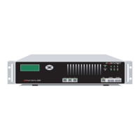
Figure 7: FortiGate-4000S rear panel
Power supplies and power connections
The FortiGate-4000 chassis contains 7 power supply modules. Each power supply
can provide a maximum of 350 watts for a total of 2100 watts, in 6+1 hot-swap
redundant configuration that includes load balancing. The voltage range is 100-230
VAC auto range.
The power connections supply AC power to the power supplies. Connect all three
power connections to power outlets. Use the power switch on the power connector
module to turn the FortiGate-4000 chassis power on and off.
Connect each power cable to a different power source, if possible. If one power
source fails, the other source might still be operative.
When power is restored after a power failure, the FortiGate unit will pause and then
restart automatically.
A power supply module is powered on when its power on LED turns green.
Figure 8 illustrates the power supply modules and the power connectors.
LAN 2LAN 1
ONON OFFOFF
ERRERR
Management
module
External ethernet
switched interface
modue
Cooling fan trays
LAN 1LAN 2COM
SFP
SFP HiGig OUT HiGig IN
ON OFF
LAN 1LAN 2COM
SFP
SFP HiGig OUT HiGig IN
ON OFF
Power
connectors
Chassis
power
switch
Power supply
modules (7)
Power switch
Power on LED
Fan housing
Locking handle
Internal ethernet
switched interfa
module
10/100 out of ba
management
module
 Loading...