39
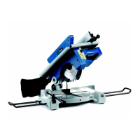
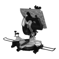
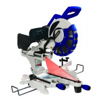
ADJUSTMENT OF CUTTING ANGLES (Fig. 9 – 10)
CHECK AND ADJUSTMENT OF CUTTING ANGLES:
If you have to carry out any adjustment, follow the instructions below:
90° horizontal and vertical
• To obtain an angle of 90° between the fence and the blade loosen the bolts (B1-B2)
located on the fence 18 by using an Allen wrench; adjust the angle by positioning a 90°
square between the fence ad the blade 7 (Fig.3); then tighten the nuts (B1-B2).
• To obtain an angle of 90° between the blade and the bench, loosen the nut and adjust
the headless screw (G1) located on the joint by using an Allen wrench; adjust the angle
by positioning a 90° square between the rotating support 5 and the blade 7 (Fig.3); then
tighten the nut.
45° horizontal and inclined
• To obtain an angle of 45° between the fence and the blade loosen the bolts (B3-B4)
located on the fence 18 by using an Allen wrench; adjust the angle by positioning a 45°
square between the fence ad the blade 7 (Fig.3); then tighten the nuts.
• To obtain an angle of 45° between the blade and the bench, loosen the nut and adjust
the headless screw (G2) located on the joint by using an Allen wrench; adjust the angle
by positioning a 45° square between the rotating support 5 and the blade 7 (Fig.3); then
tighten the nut.
FIXING THE MITRE SAW TO A BEARING SURFACE (Fig.11)
Place the machine on a bench or on a base / trestle which is plane enough, in order that the
machine is stable enough.
In order to work while taking into account ergonomic criteria, bench's or base’s height must
allow you to place the base plane or the upper workbench between 90 ad 95 cm from the floor
(Fig. 11)
.
It is recommended to place the machine in the working area in order that the surrounding area
of the machine is 80 cm at least, in order to carry out any cleaning, maintenance and necessary
Fig. 9 Fig. 10