20
IT
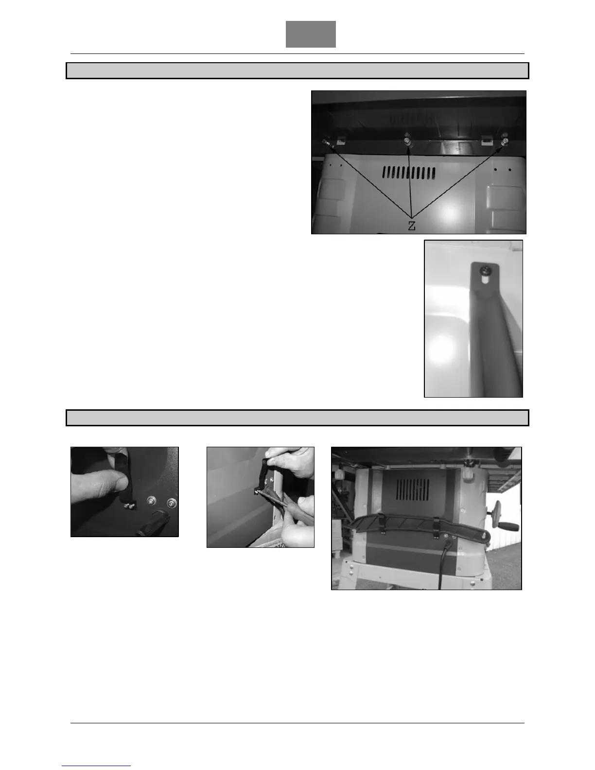
MONTAGGIO DELL’ESTENSIONE POSTERIORE DEL PIANO DI LAVORO
1. Utilizzate le 3 viti M5 x 16 mm, ognuna con una
rondella e una rondella freno (Z) per fissare
l’estensione (F) al piano di lavoro del banco sega.
2. Utilizzate le due viti M5 x 20 mm con le rondelle per
fissare i pezzi di appoggio (L) sul telaio del banco
sega.
3. Utilizzate le due viti M5 x 20 mm con le rondelle e i
dadi per fissare i pezzi di appoggio sull’estensione
posteriore (F).
MONTAGGIO DEI SUPPORTI DELLO SPINGIPEZZO
Per montare i supporti dello spingipezzo, osservate le seguenti foto.
1 2
3