63
EN
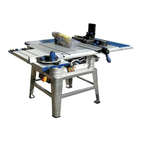
2. Then place the horizontal clamp (the long plastic piece) in the hole of the metal piece (Fig. 4); to this aim,
you need 2 30 mm round head square neck bolts and 2 knurled knobs. After this phase you will obtain the
assembly you can see in Fig. 6.
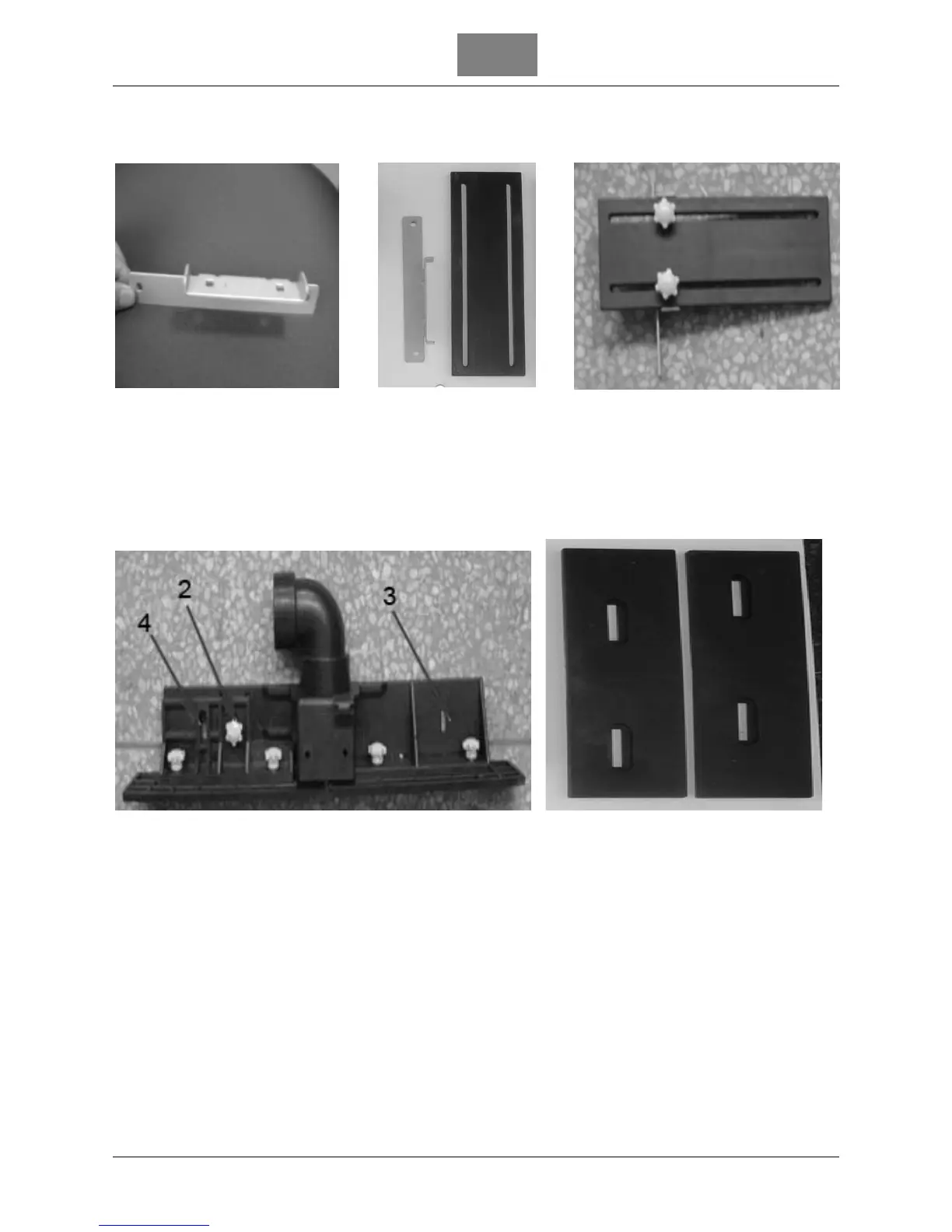
Figure 4 Figure 5 Figure 6
3. Place the two 27 mm fences on the main guide by using 4 round head square neck bolts and 4 knurled
knobs (Fig. 8).
The part 2 allows the fence to go forward. To assemble the square and the main part together you have to
use one 20 mm round head square neck bolt and one knurled knob. To fix the guide group you have to
use one 20 mm round head square neck bolt and one knurled knob for part 4; then one 40 mm round head
square neck bolt and one knurled knob for part 3 (Fig. 7).
Figure 7 Figure 8