1
4
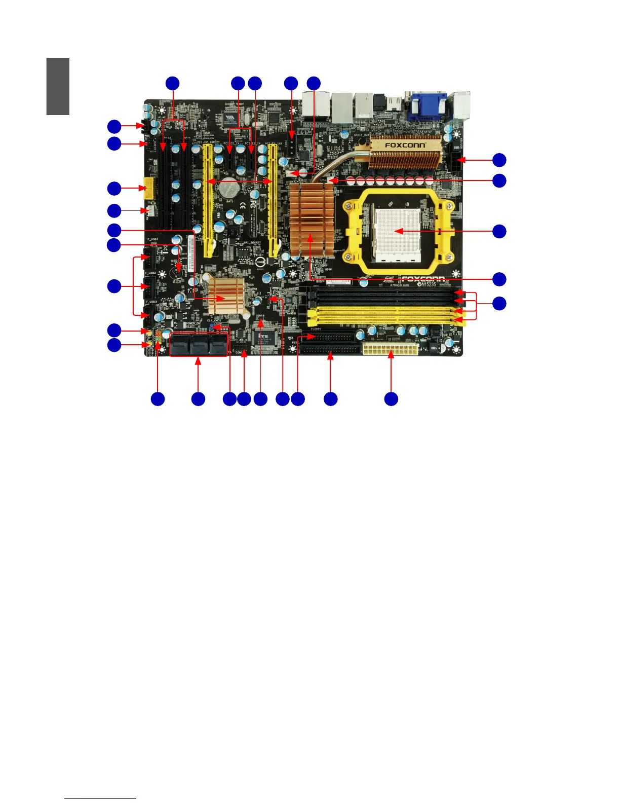
1-2 Layout
1. NB_FAN Header
2. AUX Power Connector
3. PCI Express x16 Slots
4. PCI Express x1 Slots
5. PCI Slots
6. CD_IN Connector
7. Front Audio Connector
8. 1394a Connector ( only for A7DA-S
3.0)
9. System Fan Header
10. South Bridge: AMD SB750
11. Speaker Connector
12. Front USB Connectors
13. Power on Button
14. Reset Button
15. Front Panel Connector
16. SATA Connectors
17. Clear CMOS Button
18. COM1 Connector
19. Chassis Intrusion Alarm Header
20. IrDA Connector
21. Floppy Connector
22. IDE Connector
23. 24-pin ATX Power Connector
24. DDR3 DIMM Slots
25. North Bridge: AMD RS780D
26. CPU Socket
27. CPU_FAN Header
28. 8-pin ATX 12V Power Connector
Note : The above motherboard layout is for reference only, please refer to the physical mother-
board for detail.
1816 2115
2
4
6
8
7
22
24
25
26
3
5
9
12
19 2317
10
27
1
28
11
13
14
20
 Loading...