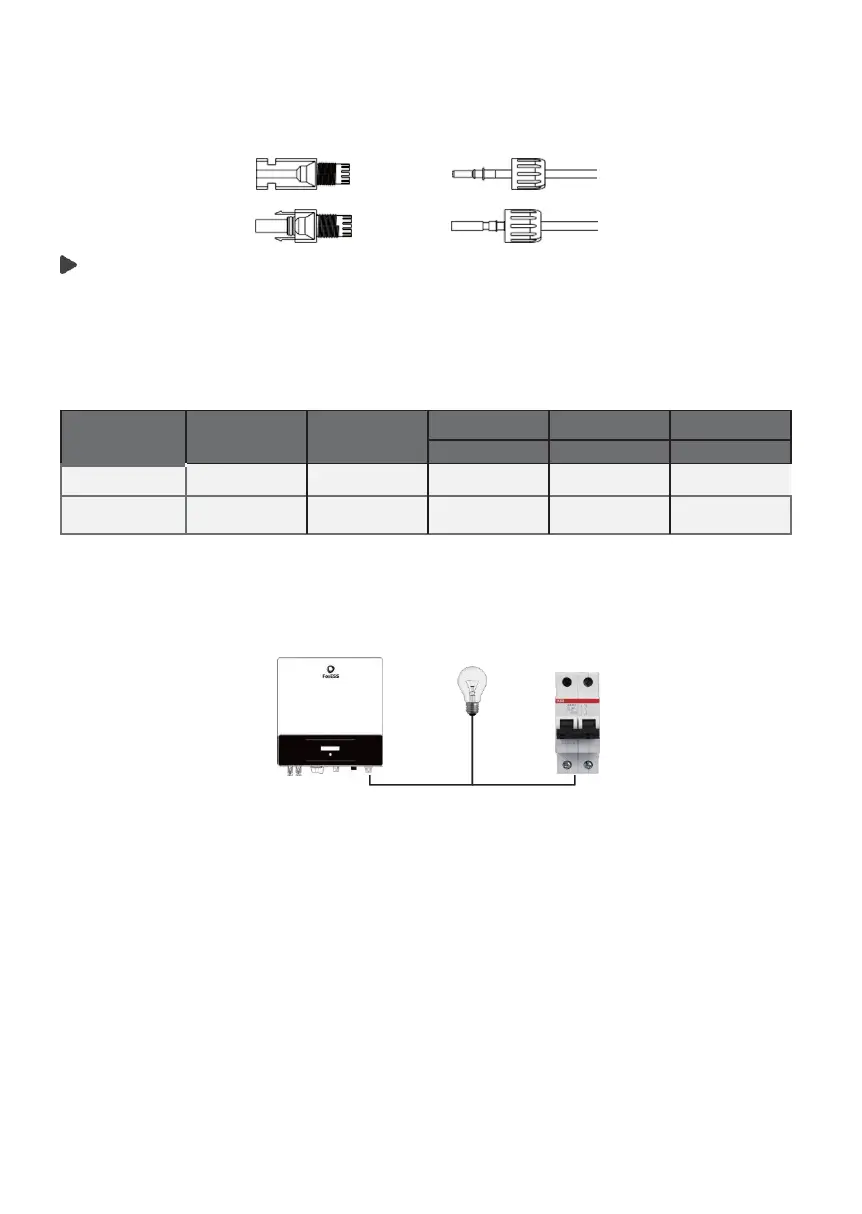
g)
Insert pin contact through the cable nut to assemble into back of the male
or female plug. When you feel or hear a “click” the pin contact assembly is
seated correctly.
Grid Connection
E/F series inverters are designed for single phase grid. Voltage range is
220/230/240V, frequency is 50/60Hz. Other technical requests should comply
with the requirement of the local public grid.
Table 4 Cable and Micro-breaker recommend-
*The parameters have some differences because of different surroundings and materials. Please refer to the
local conditions to choose appropriate cable and micro-breaker.
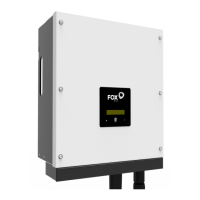
Micro-breaker should be installed between inverter and grid, any loads should
not be connected with inverter directly.
Incorrect Connection between Load and Inverter
·
Connection Steps
a)
Check the grid voltage and compare with the permissive voltage range
(refer to technical data).
b)
Disconnect the circuit-breaker from all the phases and secure against re-
connection.
c) Trim the wires:
-Trip all the wires to 52.5mm and the PE wire to 55mm.
-
Use the crimping pliers to trip 12mm of insulation from all wire ends as below.