INSTALLATION
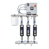
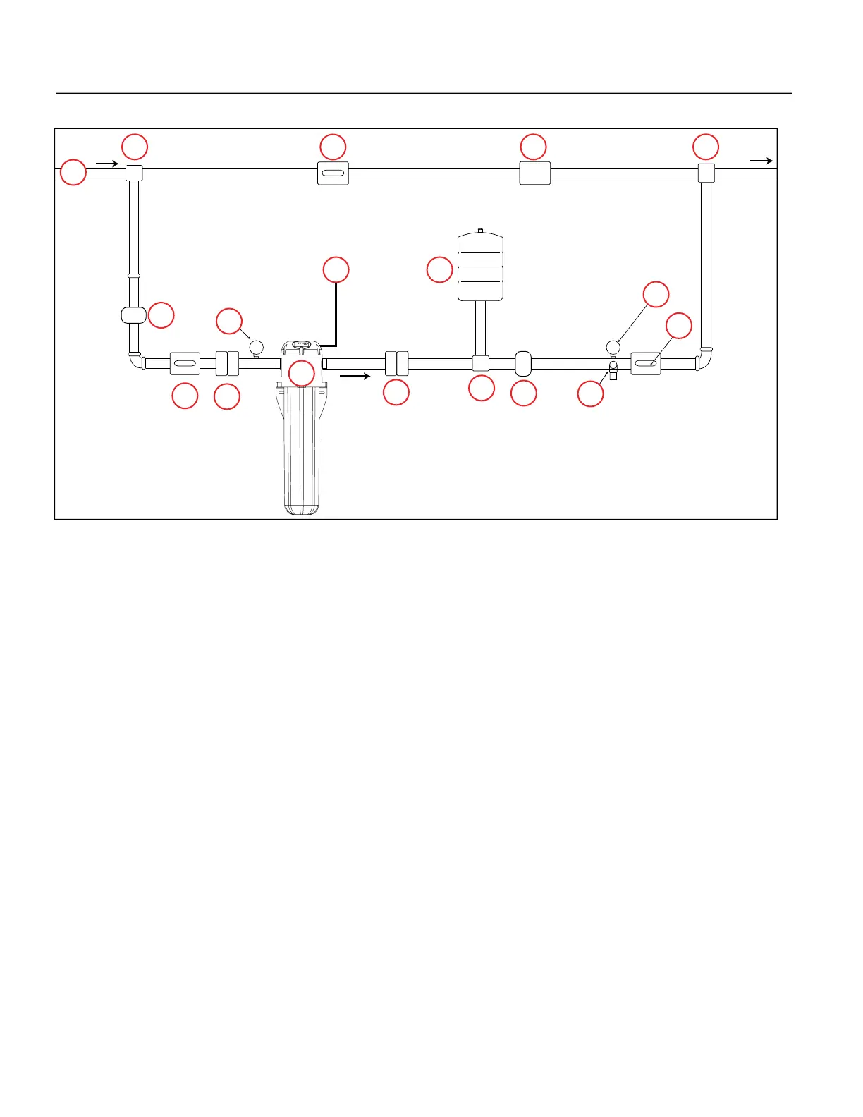
Typical Installation Diagram
10
Typical Installation Diagram
1. Water from source
2. Inline 400
3. Power Cord (No plug end on 50 Hz models)
4. Ball Valve
5. Pressure Tank (no further away than 5’ / 1.5 m from the pump)
6. Pressure Gauge
7. Inlet Pressure Reducing Valve (optional)
8. Outlet Pressure Reducing Valve (optional)
9. Pressure Relief Valve
10. Union Coupling
11. Pipe Tee
12. Check Valve
1
2
3 5
6
7
9
6
8
4
4
4
10
10
11 12
11
11

 Loading...