INSTALLATION
Plumbing Installation
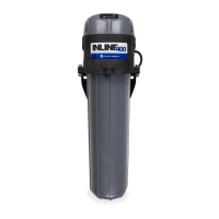
11
Plumbing Installation
1. Close all water supply valves necessary to turn off the incoming water supply. Carefully drain the exist-
ing plumbing system of all water. Make adjustments to existing plumbing to accommodate the addition
of the Inline 400 plumbing.
2. Install the Inline 400 in the desired location using mounting bracket and mounting screws, refer to
“
Inline 400 Mounting” on page 8. Screws for mounting the bracket are not included with the product.
• For ease of service, leave a clearance of 20 inches (51 cm) below the pump for housing removal.
This can be reduced if the unit is installed with two plumbing unions shown as (10) in the “
Typical
Installation Diagram” on page 10. This makes it easy to remove the entire pump from the system
for servicing.
3. Install inlet and outlet plumbing to the unit. The inlet and outlet of the Inline 400 are labeled with
“INLET” and “OUTLET” respectively. Using ball valves (4) in the system allows for a “service bypass” so
the typical household can still have incoming water if unit maintenance is required.
• Unions (10) should be installed on the suction and discharge ends of the Inline 400.
• Use of PTFE thread sealant tape is recommended over paste; do not over tighten.
• An internal check valve is provided on the discharge of the pump. This valve prevents back flow.
• If the optional bypass loop is used, a check valve (12) should also be installed in the bypass.
• Be sure to check all local plumbing codes to ensure that all requirements pertaining to back flow
prevention are met.
4. Install the
bladder-type pressure tank (5) (maximum recommended size: 2 gallon/8 liter) downstream
from the pump. The tank should be located within 5 feet (1.5 m) of the pump discharge.
• There should be no control/check valve between the pressure tank and the Inline 400.
• The tank should be charged no greater than 2 psi (0.1 bar) below the outlet pressure switch set-
ting. Factory outlet pressure switch setting is 40 psi (2.8 bar), therefore maximum tank pre-charge
is 38 psi (2.6 bar) for factory settings.
• The tank pre-charge pressure shall never exceed 80 psi (5.5 bar).
5. Install a pressure gauge (6) on both the inlet and outlet pipes. These will be required in order to prop-
erly adjust the system, as well as aid in potential system troubleshooting.
6. If the incoming supply is above 40 psi (2.8 bar), a pressure reducing valve (7) may be installed on the
inlet.
7.
The Inline 400 will boost a downstream pressure equal to 55 psi (3.8 bar) + incoming psi. If the discharge plumb-
ing, fixtures, and appliances are not rated for these higher pressures, it is recommended to install a pressure
reducing valve (8) after the pressure tank to limit the max downstream pressure.
8. Install a pressure relief valve (9) downstream of the Inline 400. This discharge must be plumbed to a
drain rated for maximum pump output at relief pressure settings.
 Loading...
