PRODUCT INFORMATION
Pump Components
6
Pump Components
What’s in the Box
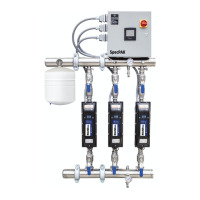
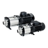
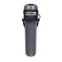
1. Inline 400 Pressure Boosting System
2. Owner’s Manual
3. Pressure Tank (if ordered as part of the system)
All Franklin Electric Inline 400 Pressure Boosting Systems are carefully tested, inspected, and
packaged to ensure their arrival in perfect condition. When the unit is received, examine it closely
to make sure there is no damage that may have occurred in shipping.
If damage is evident, report this immediately to your shipping carrier and product dealer. The ship-
ping carrier assumes full responsibility for the shipment’s safe arrival. Any claim for damage to the
shipment, either visible or concealed, must be made through the shipping carrier first.
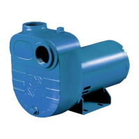
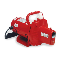
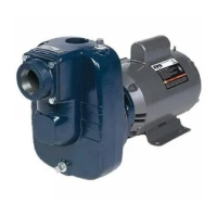
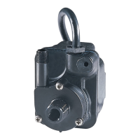
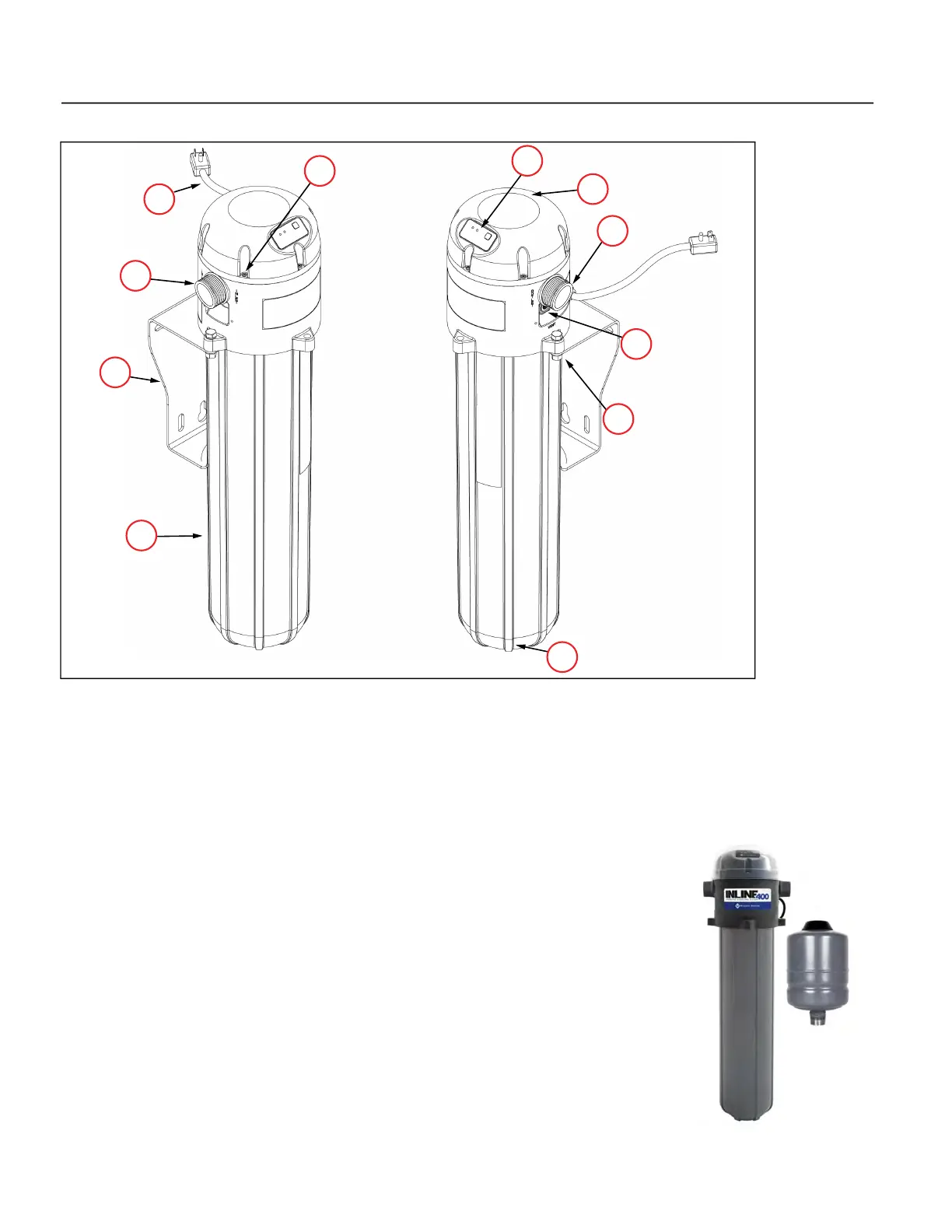
1. Head Cover Screws (6 total) 2. Power Cord (No plug end on 50 Hz models)
3. Pump Inlet 4. Mounting Bracket
5. Pump Housing 6. 1/4” NPT Drain Plug
7. Mounting Bolts (2 total) 8. Air Bleed Valve
9. Pump Outlet 10. Protective Weather Cover
11. Status Display
 Loading...