4
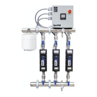
Inline Pressure Boosting System
Specications
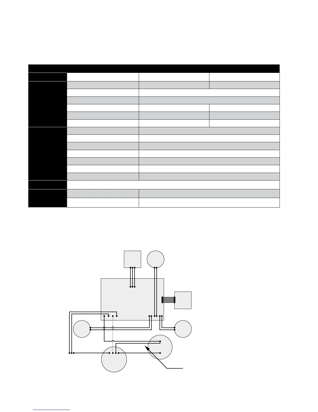
Internal Wiring Diagram
Inline 400 Inline 400
Model No.
92061501 92061502
Input from
Power Source
Voltage 115 V 230 V
Phase Single-Phase
Frequency 60 Hz
Current (max) 6.6 Amps (RMS) 3.3 Amps (RMS)
Power (max) 710 W 710 W
Wire Gauge Size(s) 18 Gauge Power Cord 18 Gauge Power Cord
Operating
Conditions
MAX ow (GPM) 20
MAX boost pressure (PSI) 55
MAX system pressure (PSI) 95
Sound Pressure Level (dB-A) <55
Plumbing Connections 1" NPT
Max Suction Lift (feet) 5
Drain Plug 1/4" NPT
Enclosure Type
Indoor Use Only / CSA Enclosure 2
Unit Size
External Dimensions 29.6" x 8.5" x 8.9"
Net Weight (lbs) 35
HALL PCB
MOTOR
MAIN PCB ASSEMBLY
CAPACITOR
BLACK WIRE FROM MAIN PCB AND BLACK WIRE
FROM MOTOR MUST BE CONNECTED TO THE
SAME CAPACITOR TERMINAL.
TEMP.
SENSOR
INCOMING
POWER
Black
Green Red
Yellow
Red (230 V)
White (115 V)
UI
PCB
PRESS.
SWITCH
IN
PRESS.
SWITCH
OUT