4
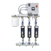
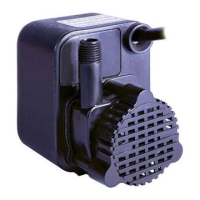
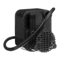
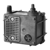
Système de surpression Inline
Spécications
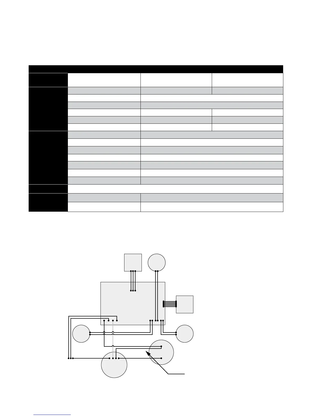
Schéma de câblage interne
Inline 400 Inline 400
Numéro de
modèle
92061501 92061502
Entrée de
l’alimentation
électrique
Voltage (V) 115 V 230 V
Phase Monophasé
Fréquence 60 Hz
Intensité (max.) 6,6 A (RMS) 3,3 A (RMS)
Puissance (max.) 710 W 710 W
Taille(s) de calibre de l Cordon d’alimentation de calibre 18 Cordon d’alimentation de calibre 18
Conditions de
fonctionnement
Débit MAX. (GPM) 20
Surpression MAX. (PSI) 55
Pression du système MAX. (PSI) 95
Niveau sonore (dbA) < 55
Connexions de plomberie NPT 1 po (25,4 mm)
Hauteur d’aspiration max. (pi) 5
Bouchon de vidange NPT ¼ po (6,35 mm)
Type de boîtier
Utilisation intérieure seulement / Boîtier CSA 2
Dimensions
de l’unité
Dimensions extérieures 29,6 po x 8,5 po x 8,9 po (75,2 cm x 21,6 cm x 22,6 cm)
Poids net (lb) 35
PCB HALL
MOTEUR
ASSEMBLAGE PCB PRINCIPALE
CONDENSATEUR
LE FIL NOIR DE LA PCB PRINCIPALE ET LE FIL
NOIR DU MOTEUR DOIVENT ÊTRE BRANCHÉS
À LA MÊME BORNE DE CONDENSATEUR.
CAPTEUR
TEMP.
ALIMENT.
ENTRANTE
Noir
Vert Rouge
Jaune
Rouge (230 V)
Blanc (115 V)
PCB
IU
ENTRÉE
INTERR.
PRESSION
SORTIE
INTERR.
PRESSION