8
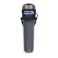
Inline Pressure Boosting System
Union
Coupling
2 Gallon
Tank
(Discharge into drain
rated for max pump
output at relief pressure)
Pressure
Gauge
Pressure
Gauge
Pressure
Reducing Valve
(optional)
Pressure
Relief
Valve
Union
Coupling
Ball
Valve
Ball
Valve
Inline Pressure
Boosting System
Power
Check
Valve
5 feet or less
Flow
Pressure
Reducing Valve
(Optional)
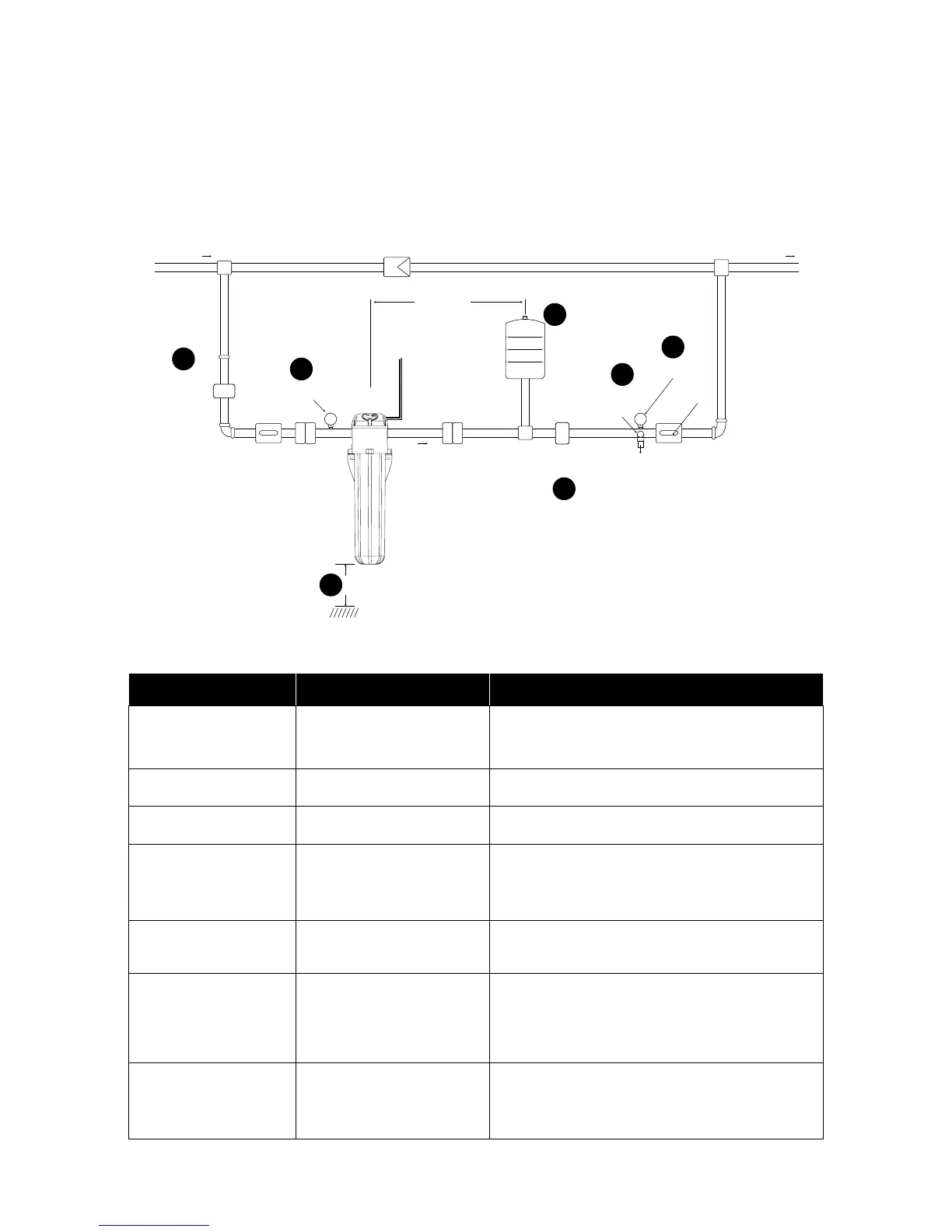
*It is recommended (where applicable) to install the Inline 400 pump
in PARALLEL with the incoming water supply. This will allow for a “ser-
vice bypass” so that the typical household can still utilize the incoming
water (albeit at a reduced pressure) if maintenance work is required.
This type of installation requires both ball valves and the check valve
be installed as shown above.
A
F
C
B
D
G
E
Figure 1
Inline 400 Typical Residential Installation:
The Inline Pressure Boosting System is designed to increase a system's usable pressure
whenever water is in use. Shown below is a diagram of the “required” and “recommended”
components of a typical pressure boosting application.
#
System Component Description
A
Pressure Tank
A bladder-type pressure tank is required (recommend 2 gallon
size) for proper control of the Inline 400. See "Frequently asked
Questions" section for more detail. It is important that a check
valve NOT be installed between the pump and the pressure tank.
B
INLET Pressure Gauge
An INLET pressure gauge is recommended for the purpose of
system setup, operation, and troubleshooting.
C
OUTLET Pressure Gauge
An OUTLET pressure gauge is recommended for the purpose of
system setup, operation, and troubleshooting.
D
Outlet Pressure Reducing Valve
(PRV)
This Inline 400 will boost a downstream pressure equal to
55 PSI + incoming PSI. If the discharge plumbing, xtures,
and appliances are not rated for these higher pressures, it is
recommended to install a PRV after the pressure tank to limit the
max downstream pressure.
E
Inlet Pressure Reducing Valve
(PRV)
This Inline 400 will not function if the incoming water pressure
is greater than 40 PSI. If the incoming supply is above 40 PSI, a
PRV may be installed on the inlet.
F
Outlet Pressure Relief Valve
It is recommended to install a pressure relief valve in the
discharge plumbing in order to protect the downstream
components from abnormal pressure spikes that may occur in
certain applications. Make certain the valves discharge is directed
towards a drain appropriately sized for the max ow of the pump
system or incoming water supply.
G
Mounting Clearance
For ease of service, it is recommended to leave a clearance of
20 inches below the pump (for housing removal only). This can
be reduced if the unit is installed with the two plumbing unions
shown above. This would make it easy to remove the entire pump
from the system for servicing.