FP4000 Rev0204
16
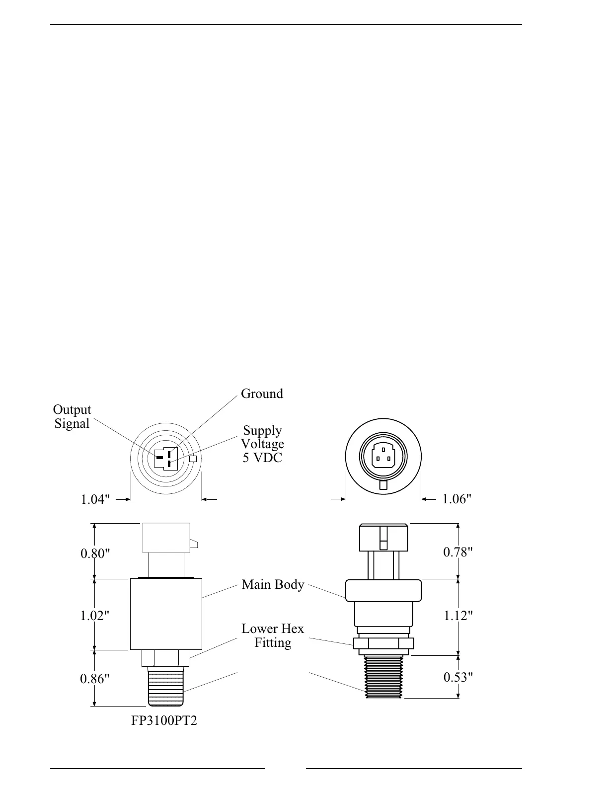
Caution: Do not use the main body
that houses the electronics to tighten
the transducer. Damage to the
transducer may occur.
Figure 6. Pressure Transducer
Install Pressure Transducer
The pressure transducer is mounted on the downstream side of the discharge valve.
Pressure transducers are interchangeable. It is recommended that the calibration
be checked if pressure transducers are swapped.
Note: Install the pressure transducer upright so water in the end of the pressure
transducer is able to drain back into the pipe.
1. Screw the transducer into a 1/4-18 NPT hole.
Caution: Do not use the main body that houses the electronics to tighten the
pressure transducer. Damage to the transducer may occur.
2. Tighten the transducer with a 9/16-inch (3/4 for alternate part) wrench on the
lower hex fitting.
3. Connect the pressure transducer cable from the display module to the pressure
transducer (the cable is color coded red). (Refer to Wiring section.)
1/4-18 NPT
1234567890
1234567890
1234567890
1234567890
1234567890
1234567890
1234567890
1234567890
1234567890
1234567890
1234567890
Lower Hex
Fitting
Supply
Voltage
5 VDC
Output
Signal
Ground
Main Body
1.04"
1.06"
1.02"
0.86"
0.80"
0.53"
0.78"
1.12"
FP3100PT2 FP4000PT1
Alternate Part

 Loading...
