FP4000 Rev0204
32
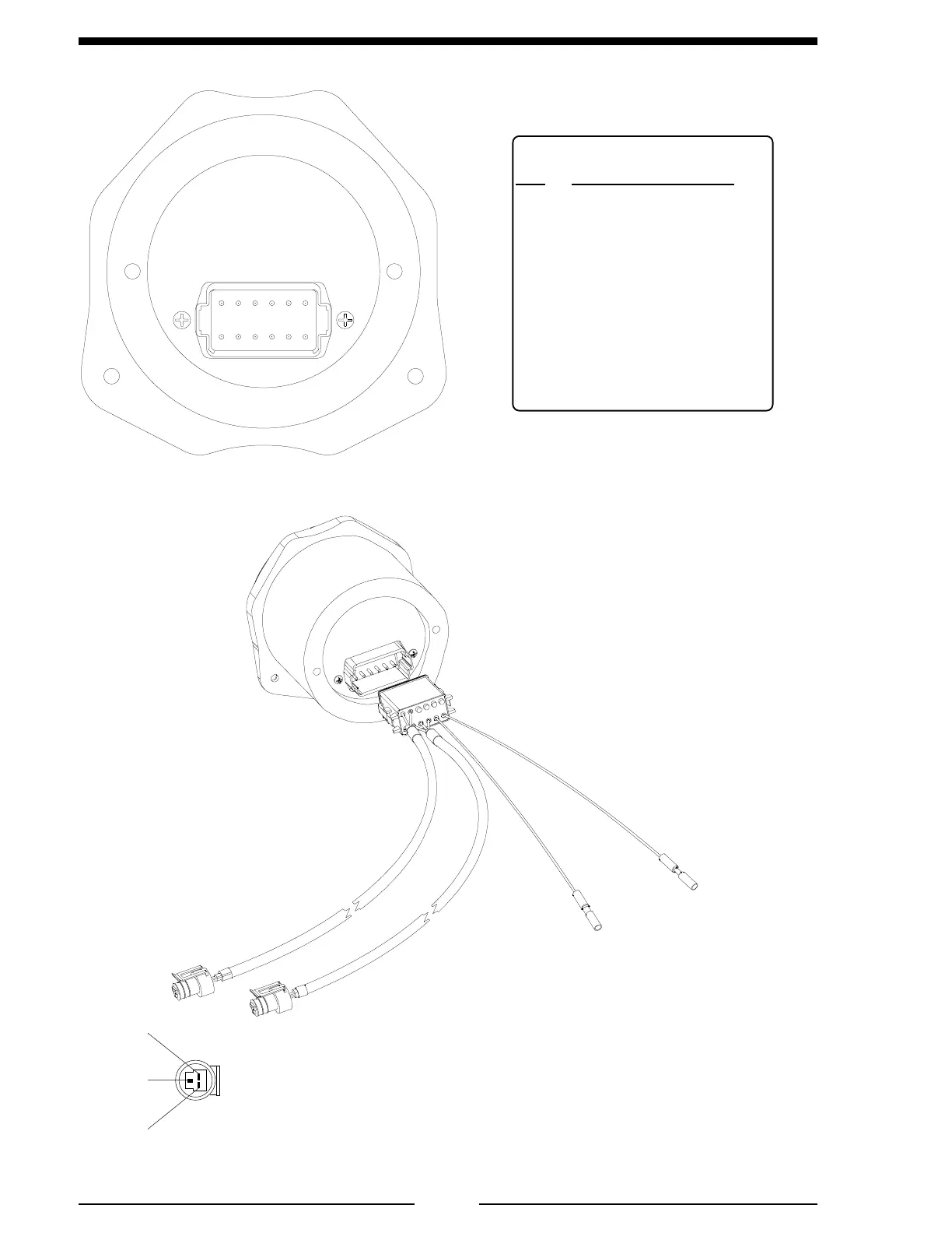
WIRING
Figure 9. Primary Display Wiring
Note: Connect the black ground wire
(pin 2) to battery negative (–) or a
good chassis ground (the chassis
ground should have a resistance less
than 1 ohm to the battery negative).
Black Wire
Ground
Red Wire
9 - 30 VDC
To Pressure
Transducer
Color Coded
RED
To Flow
Sensor
Color Coded
BLUE
Note: Minimum
wire size for power
is 18 AWG.
FP4000 Connector
Pin Signal Description
1 Power 9 - 30 VDC
2 Ground
3 Flow Sensor 5 VDC
4 Flow Sensor Ground
5 Flow Sensor Signal
6 Pressure Sensor 5 VDC
7 Pressure Sensor Ground
8 Pressure Sensor Signal
9 NC
10 External Totalizer Button
11 Datalink CAN Low
12 Datalink CAN High
Primary
Display
1
127
6
5 VDC
Output
Signal
Ground
Connector
Pinouts

 Loading...
