© Safe Fleet | September 2018 | All rights reserved
Document #: XE-SNB1-Install-PM-R0A
p. 9
inView 360 Fusion Installation Guide
Installing Power & Interface Components
Installing Power & Interface Components
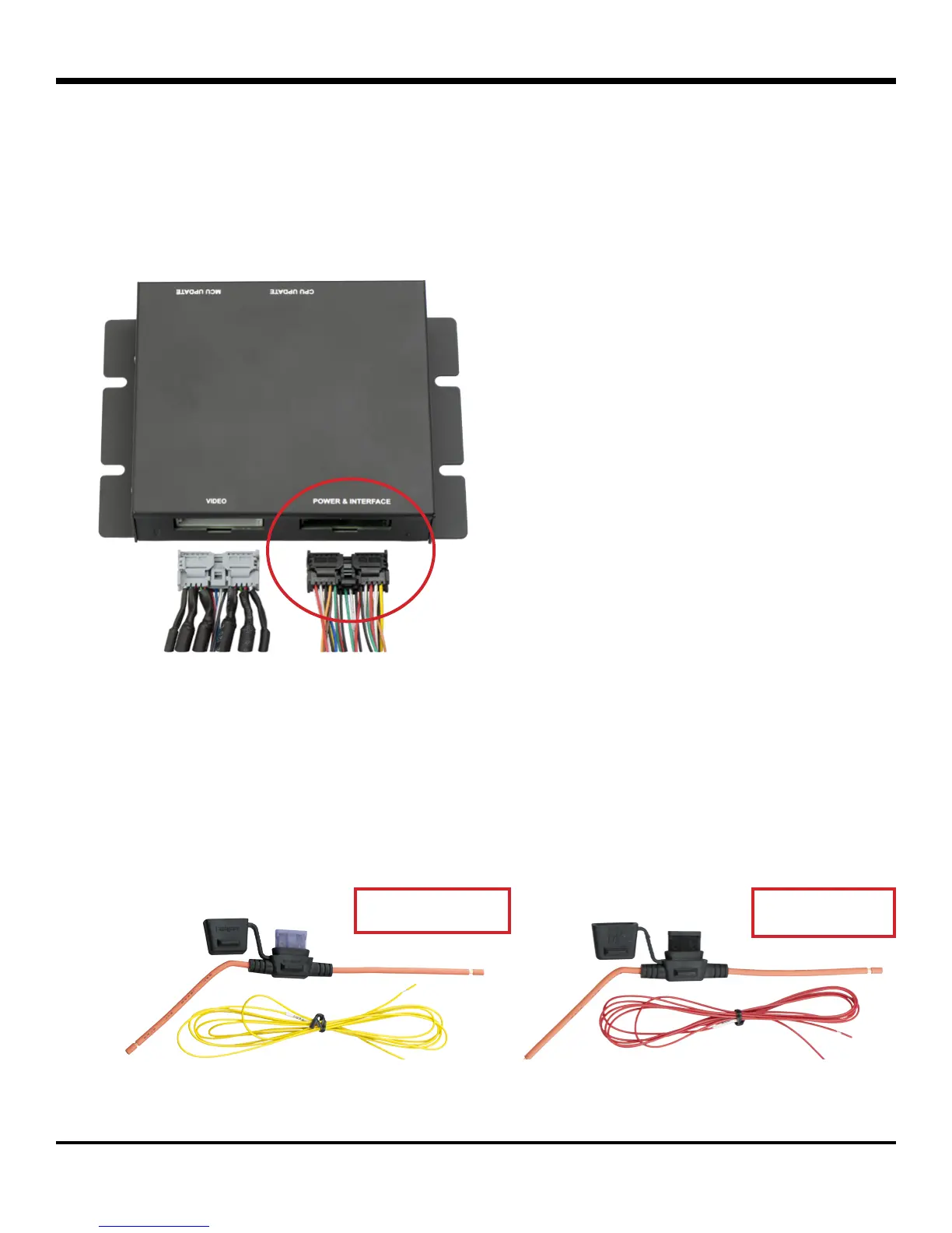
Installing the harness
The Power & Interface harness connects the ECU to the vehicle’s power, ignition, ground, and directional signals (left,
right, reverse)� In addition, the harness provides power to the AVM’s remote control sensor and driver button�
To install the harness properly:
• Connect the GND (Black) wire to an appropriate vehicle ground source.
• Connect the VBAT (Yellow) wire to the vehicle’s constant power source via the 3A fuse�
• Connect the ACC (Red) wire to the vehicle’s ignition source via the 1A fuse�
ACC w/1A FuseVBAT w/3A Fuse
 Loading...