Part No. 90-0113-00
Fdmman2.p65 2/98
Do not connect incoming AC from any
source to the AC output of the inverter/
charger. This is known as back-feeding
and will damage the unit and void the
warranty.
WARNING
bonded together. This technique insures
safety in all conditions and conforms to the
requirements of the NEC.
For detailed information, refer to the
separate Installation Guide.
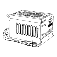
AC Wiring
The AC wires route through the strain
relief holes in the bottom of the unit. Use a
screwdriver to remove the screws which
secure the AC wiring compartment cover
plate. Inside, the compartment is divided into
2 sections, one labeled AC Input, the other
labeled AC Output. Each side contains 3 (6*)
pigtails: black, white and green.
Black. . . . . . . . .Hot or Line
White. . . . . . . . .Neutral
Green. . . . . . . . Ground
Conventional metal strain reliefs are
provided. These can be replaced with plastic
strain reliefs for additional corrosion resis-
tance or 3/4 inch conduit fittings (1/2 inch for
Freedom 10) if the wiring will be routed
through a conduit.
You must use 10 AWG copper wire with
insulation rated for 60 degrees centigrade or
higher for both the AC input and AC output.
INSTALLATION
AC Input: Feed the 3 conductor AC
input wire through the strain relief and into the
AC input compartment. You should have 6
inches of individual insulated black, white and
green wire. Strip 1/2 inch of insulation off
each conductor and connect to the pigtails:
Black to Black, White to White, and Green to
Green.
Use the wire nuts provided to make the
wire connections. You may chose to use butt
splices (not included) to make the wire
connections.
*Freedom 25 has 2 AC inputs.
Freedom 20D has 2 AC outputs.
22
NOTE: Freedom 25 Only. There are
two options for configuring the AC input to
the Freedom 25.
Dual Inputs: You may feed the
internal battery charger separately from
the transfer input which feeds the AC
loads. In this case, connect one 30 Amp
feed to the charger pigtails and another 30
Amp feed to the transfer switch input.
The advantage is to balance the AC
loads when 2 legs of incoming AC power
are available. These two feeds can be in
or out of phase. Transfer will only occur
when power is applied to both inputs.
The charger can draw up to 27 Amps on
one leg of power and the transfer switch
can pass up to 30 Amps from the other leg
of power.
Single Input: Feed both the battery
charger and the transfer switch from the
same AC input. In this case you will
connect both pigtails together, Black to
Black, White to White and Green to
Green.