Part No. 90-0113-00
Fdmman2.p65 2/98
REMOTE CONTROL PANEL
Remote Control Wiring
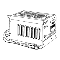
The Freedom Remote Control Panel is
supplied with 25 or 50 feet of telephone cable
for connection to the unit. Simply plug one
end of the cable into the remote connector on
the bottom of the inverter/charger labeled
“Remote” and the other end into the
connector on the back of the Freedom
Remote Control Panel.
Routing the remote cable away from AC
and DC wires will minimize the potential for
interference which may affect the LED
bargraphs.
The remote control cable can be
extended up to 50 feet if required. Use
standard 4 or 6 conductor telephone cable.
Use a single length cable with no connnectors
or in-line splices. If phone cable is left over,
wrap excess wire in a figure 8 configuration
and store it in an area away from AC
equipment to prevent electrical interference.
Once the above steps have been
completed, the unit can be bolted down.
Refer to page 33 for the Dip Switch
Programming chart.
NOTE: Freedom 25 only. If feeding both
inputs with one 30 Amp breaker, set Power
Sharing to 30 Amps.
Dip Switch Status
You can check the position of the dip
switches by quickly cycling the power switch
OFF/ON twice. The DC Volts bargraph will
cease to display battery voltage and will indi-
cate the settings of each dip switch. In this
mode the bottom LED will illuminate if switch
1 is ON; the second LED will illuminate if
switch 2 is ON, etc. Dip switch settings are
indicated for 10 seconds after which time the
display returns to indicating battery voltage.
Factory default settings for all dip
switches are in the OFF position.
32