Part No. 90-0113-00
Fdmman2.p65 2/98
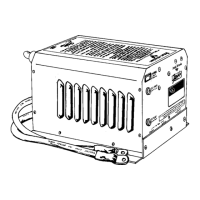
7. Keep the inverter/charger out of the
elements and out of direct contact with
water or spray. Failing to do so may result in
premature failure from corrosion and void the
warranty.
11. You may mount the unit horizontally (on
a shelf) or vertically (on a wall or bulkhead).
If mounted vertically, you must orient the unit
so the switch and the circuit breakers are
facing up and the fan and battery cables are
facing down.
12. Allow several inches of clearance
around the unit to permit a supply of fresh air
to the cooling fan. Do not block any of the
vents or louvers. The thermostat controlled
fan pulls air from outside the unit. It blows air
across the internal components, particularly
the transformer and heat sinks, then out the
side vents.
13. If installing in a system which includes an
existing battery charger or converter, make
sure these do not operate from the inverter
output AC power. This sets up a power loop
which, due to inefficiencies, will quickly drain
the batteries.
14. DC wiring is generally very simple, the
positive and negative cables from the inverter/
charger are connected to the house or
auxiliary battery. In the case of multiple
batteries, the interconnecting jumper cables
must be of the same AWG as those supplied
with the inverter/ charger.
15. If multiple battery banks are to be
charged, a battery selector switch can be
installed, allowing the banks to be charged
either individually or simultaneously. A
solenoid can also be used.
INSTALLATION
8. Mount the unit as close to the batteries
as possible but not in the presence of
flammable fumes or in an enclosed battery
compartment.
9. Keep the overall length of each battery
cable less than 10 feet. If needed, attach
short extension cables. Do not use frame
ground or a ground bonding system as a
current carrying conductor. Run the negative
cable directly to the battery bank. If the
positive and negative cables run parallel to
each other, twist the cables together. This will
minimize the adverse effects of inductance. If
it is absolutely necessary to run cable more
than 10 feet, increase the size of the cable.
10. The connectors for the Freedom
Remote Control, Link Instrument and the
chassis ground bonding lug, as well as for
the AC wires, are located on the bottom of
the unit. Be sure to make these connections
before bolting down the unit.
Do not mount the unit in an enclosed
battery compartment. Take precautions to
keep road dirt and spray off the unit.
WARNING
20