Part No. 90-0113-00
Fdmman2.p65 2/98
The Freedom Inverter/Charger provides
household 120 Volt AC power from auxiliary
DC batteries, automatic battery charging and
automatic AC transfer switching.
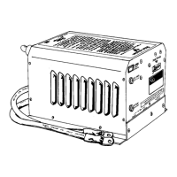
Power Switch
The Power Switch is located on the front
panel. This switch controls ON/OFF and
RESET for the inverter.
If the unit is connected to external AC
power, the battery charger and transfer switch
will continue to function, regardless of the
position of the switch.
OPERATION
Power Switch
When external AC power is removed
and the power switch is in the ON position,
the inverter will automatically be ON. If the
switch is in the OFF position and external AC
power is removed, the inverter will be OFF.
Inverter overload protection, transfer
switching, default Power Sharing and 3-stage
battery charger regulation will all function
automatically.
If installed with the Freedom Remote
Control Panel or Link Instrument, the power
switch on the unit should be left in the OFF
position. Refer to Freedom Remote Control
Panel Addendum, pages 28-34, or the Link
Owner’s Manual.
Freedom 10 and 20 Circuit Breakers
INPUT
INV/CHG
Freedom 25 Circuit Breakers
CHARGER
TRANSFER
OUTPUT
Freedom 25 shown.
7