Part No. 90-0113-00
Fdmman2.p65 2/98
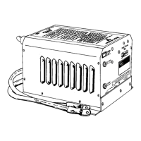
REMOTE CONTROL PANEL
To successfully charge an over dis-
charged battery, you must remove as much
DC load as possible. Set dip switches 7 and 8
to the ON position to limit the amount of
charge current and the resulting ripple
voltage. After the battery voltage has reached
10 Volts, these switches can be set to their
previous positions.
Use the 5 Amp Power Sharing setting for
small generators, or for charging deeply
discharged batteries.
temperature dependent. For these reasons,
the dip switches allow four different battery
charger voltage set points, depending on
battery type and ambient temperature:
Cool Wet Cell . . . . < 80 degrees F.
Warm Wet Cell . . . > 80 degrees F.
Cool Gel Cell . . . . .< 80 degrees F.
Warm Gel Cell . . . .> 80 degrees F.
Refer to the table on page 17 for the
specific voltages for each setting.
SWITCH
#4 - Auto Charge
With the switch in
the OFF position, the remote panel ON/OFF
switch only controls the inverter operation.
With the dip switch turned ON, it allows the
power ON/OFF switch on the front of the
remote to control the battery charger as well
as the inverter.
SWITCH #5 & #6 -
Idle Sensitivity
Most
installations will be connected to the electrical
system, which in itself, with no appliances
turned on, represents a small load. Using a
trial and error process, the idle ciruit can be
adjusted until the unit will detect small loads
but still drop into idle mode when all loads are
shut off.
NOTE: Some small loads may not pull
the unit out of idle mode. If this occurs, you
may disable the idle circuit or use an addi-
tional load (i.e., a small incandescent light) to
first activate the idle circuitry. You can confirm
the unit is in idle mode by checking the DC
Amps bargraph. The lowest LED goes out
when the unit is in idle mode.
A Volt meter can be used to confirm the
idle condition. Idle mode output voltage will
typically measure between 10 and 55 Volts
with an averaging AC Volt meter. See the
Troubleshooting chart, page 27, for a
discussion of measuring inverter output
voltage with a meter.
SWITCH #7 & #8
- Power Sharing
These switches should be set to match the
value of the circuit breaker which protects the
incoming AC power. They may also limit the
output current from the battery charger.
31
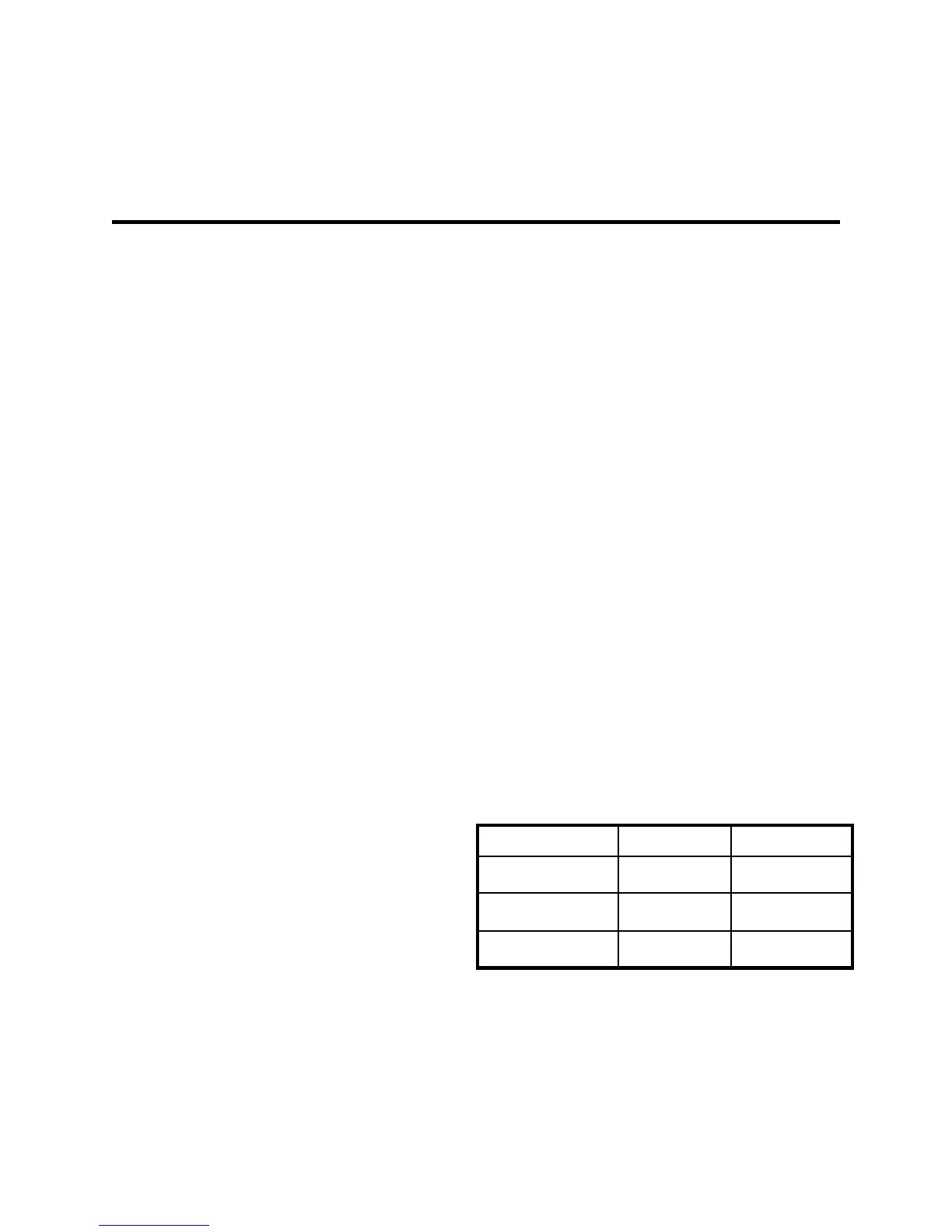
System DC
Current Consumption vs Idle Mode
Normal Idle
Idle Circuit Disabled
Unit Shut Off
Idle Mode
With Remote Without Remote
181 mA
120 mA
496 mA N/A
16 mA 7 mA