12. Remove the coolant filter with a strap or chain
wrench. Install a new coolant filter and tighten.
13. Fill the cooling system with new coolant. The
cooling system is filled when the coolant level
reaches the MAX line on the surge tank. Refer to
the engine manufacturer’s service literature for
specific coolant information.
14. Replace the surge tank cap(s).
15. Return the hood to the operating position.
16. Start the engine and turn on the cab heater.
Allow the engine to warm up to normal operating
temperature. Check the radiator and hoses for
leaks. Repair as needed.
17. Shut off the engine, then check the coolant level
in the surge tank. Add coolant if the level isn’t at
the MAX line on the surge tank.
20–03 Fan Clutch Check (Noise
Emission Control)
Borg Warner (Kysor) K26RA Fan
Clutch
1. Disconnect the batteries at the negative termi-
nals. Drain all air from the air system.
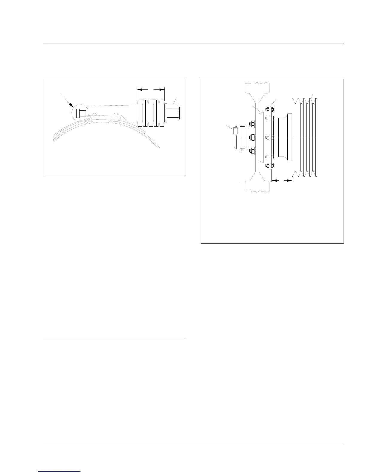
2. Measure the distance from the back surface of
the fan clutch retaining plate to the forward-most
edge of the fan belt pulley. See
Fig. 5, Ref. A.
3. Disconnect the line from the air inlet of the air
cylinder. Connect a shop air hose to the inlet.
4. Apply a minimum of 100 psi (690 kPa) air pres-
sure to the air cylinder—the bearing housing will
move backwards, disengaging the clutch. Again,
measure the distance from the back surface of
the retaining plate to the forward-most edge of
the fan belt pulley.
5. Compare the two measurements; if the difference
between the two measurements exceeds 0.150
inches (3.8 mm), the clutch lining is worn and
must be replaced. See Group 20 of the vehicle
Workshop Manual for clutch lining replacement
instructions.
6. Release the air pressure, then disconnect the
shop hose from the air inlet of the air cylinder.
Connect the vehicle air hose to the inlet.
7. Connect the battery cables. Start the engine.
Horton DriveMaster® Fan Clutch
NOTE: If any part of the fan clutch needs to be
repaired or replaced after performing the checks
below, see Group 20 of the vehicle Workshop
Manual.
08/15/94
f200286
A
B
1
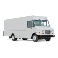
A. The screw tip must extend about 1/4 inch (6 mm).
B. Belleville washers must collapse almost flat.
1. Tightening Screw Hex
Fig. 4, Breeze Constant-Torque Hose Clamp Installation
f200237a
1
2
3
4
5
6
05/27/93
A
With the fan clutch engaged, measure the distance at A;
measure it again with the fan clutch disengaged.
1. Bearing Housing
2. Retaining Plate
3. Fan Pulley
4. Air Inlet (from solenoid
valve)
5. Air Cylinder
6. Fan
Fig. 5, Kysor K26RA Fan Clutch Lining Wear Check
Engine Cooling/Radiator 20
Cascadia Maintenance Manual, August 2015 20/3
 Loading...