lights, and a driver display screen. The driver display
screen is a one-line by seven-character liquid crystal
display (LCD) that normally shows odometer read-
ings.
There are four rows of lights in the dash message
center. Lights installed in the top row are optional
and their positions may vary. The lights in the bottom
three rows are installed in fixed positions on all ve-
hicles. Most are standard, but a few are optional.
See Fig. 2.8 and Fig. 2.9.
NOTE: The functions of the ABS/ATC warning
lights are explained under "Meritor WABCO An-
tilock Braking System (ABS)", later in this chap-
ter.
NOTE: The amber LANE SRCHNG warning
light for the optional Lane Guidance
™
System is
explained later in this chapter.
Buzzer
A buzzer sounds for three seconds during the self-
test at start-up, and when the following conditions
exist:
•
low air pressure
•
low oil pressure
•
high coolant temperature
•
the parking brake is applied and the vehicle is
moving at a speed of at least 2 mph (3 km/h)
ICU3/ICU3 ’07 Ignition Sequence
If the headlights are turned on, the screen displays
the odometer and waits for the ignition to be turned
on.
When the ignition is turned on, all the electronic
gauges complete a full sweep of their dials, the
warning and indicator lights light up, and the buzzer
sounds for three seconds.
NOTE: The air gauges do not sweep.
The following lights illuminate during the ignition se-
quence:
•
Fasten Seat Belt Warning
•
Low Battery Voltage Warning
•
High Coolant Temperature Warning
•
Low Engine Oil Pressure Warning
•
Low Air Pressure Warning
•
Parking Brake On Indicator
•
All engine warning lights, including engine pro-
tection, check engine, and (Cummins only)
stop engine
•
All ABS warning lights, including wheel spin,
tractor ABS, and (if installed) trailer ABS
See Fig. 2.10 for the ICU3/ICU3 ’07 ignition
sequence.
NOTE: Although the engine and ABS warning
lights illuminate during the ignition sequence,
they are not controlled by the ICU, but by their
own system ECU (electronic control unit).
When the ignition switch has been turned on, the
ICU3 performs a self-test, looking for active faults.
During the first half of the self-test, all segments of
the display illuminate as follows: 888888.8. The ICU3
voltmeter display also illuminates, but with the value
18.8. During the second half of the self-test, the soft-
ware revision level is displayed.
f610205b06/02/99
0
5
10
15
20
30
RPM
5
15
25
35
45
55
65
75
85
MPH
km/h
25
X100
30
50
70
90
130
110
10
E
F
1/2
0
100
50
PSI
WATER
OIL
TRANS
FUEL
AIR
AIR
100
150
200
250
F°
100
225
350
F°
0
150
50
PSI
100
0
150
50
PSI
100
1
2
3
4
5
6
7
8
9
10
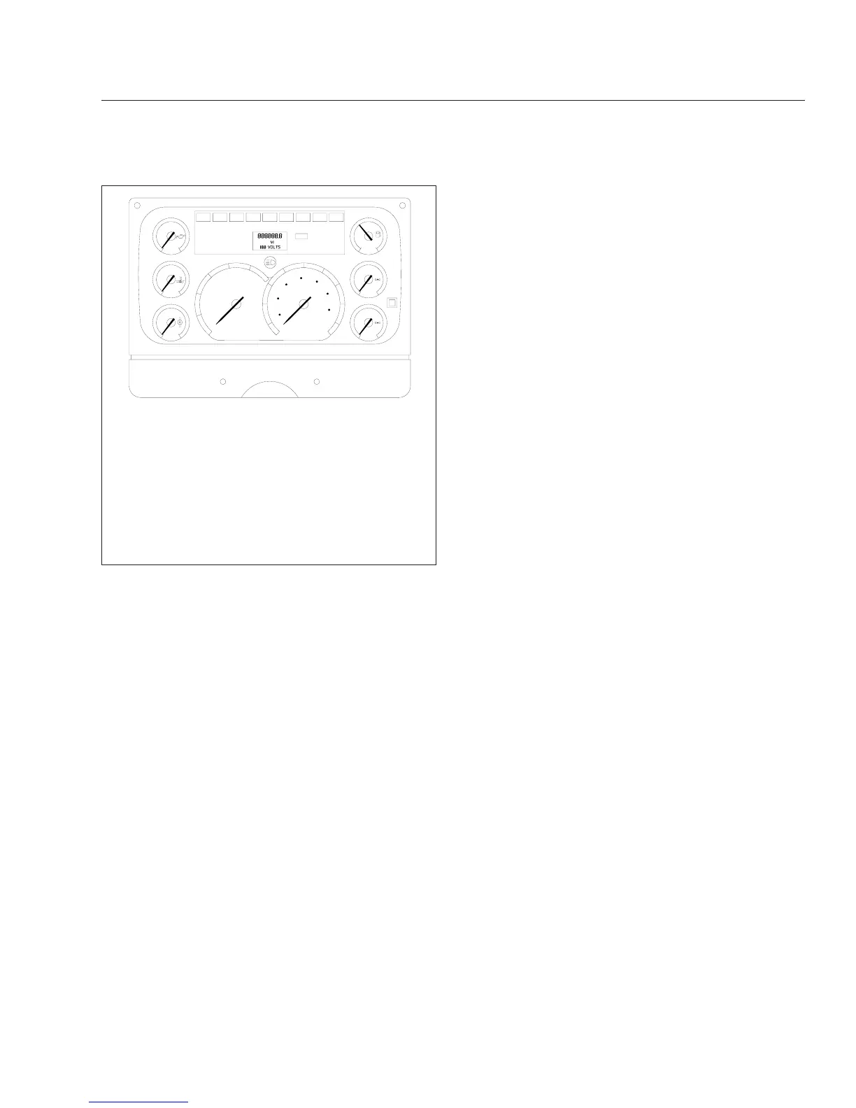
1. Transmission Temperature Gauge
2. Water Temperature Gauge
3. Engine Oil Pressure Gauge
4. Dash Message Center
5. Fuel Gauge
6. Primary Air Pressure Gauge
7. Optional Mode/Reset Push Button
8. Secondary Air Pressure Gauge
9. Speedometer
10. Tachometer
Fig. 2.7, ICU3/ICU3 ’07 Gauge Layout (ICU3 shown)
Instruments and Controls Identification
2.8