the vehicle down and bring it to a gradual stop.
Do not attempt to move the vehicle until air pres-
sure has risen above the minimum level. Moving
a vehicle without adequate braking power could
cause an accident resulting in property damage,
personal injury, or death.
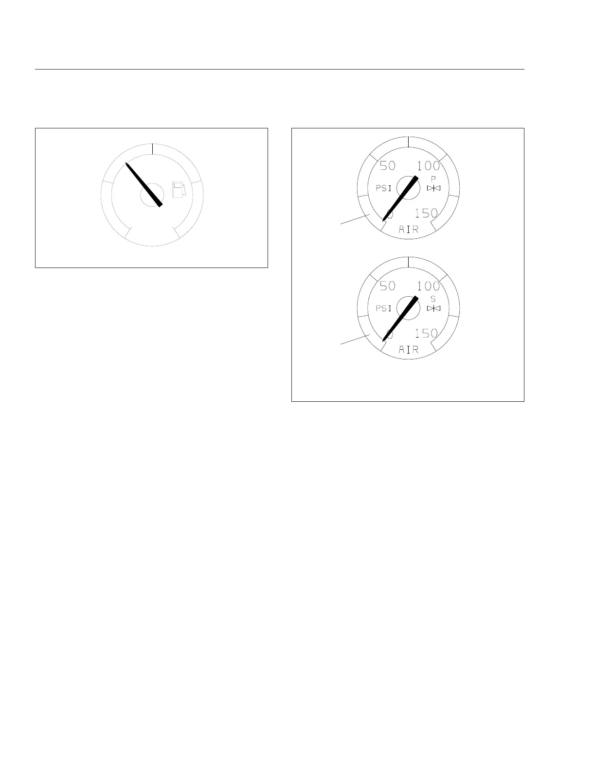
Air pressure gauges register the pressure in the pri-
mary and secondary air systems. Normal pressure
with the engine running is 100 to 120 psi (690 to 827
kPa) in both systems. See
Fig. 3.14.
Air pressure gauges are required on all vehicles with
air brakes. A low-air-pressure warning light and
buzzer, connected to both the primary and secondary
systems, activate when air pressure in either system
drops below a minimum pressure of 65 to 75 psi
(448 to 517 kPa).
When the engine is started, the warning light and
buzzer remain on until air pressure in both systems
exceeds minimum pressure.
Voltmeter
The voltmeter is a digital readout located on the bot-
tom line of the driver display screen whenever the
ignition switch is turned on.
It indicates the vehicle charging system voltage when
the engine is running and the battery voltage when
the engine is stopped. By monitoring the voltmeter,
the driver can be aware of potential charging system
problems and have them fixed before the batteries
discharge enough to create starting difficulties.
The voltmeter will normally show approximately 13.7
to 14.1 volts when the engine is running. The voltage
of a fully charged battery is 12.7 to 12.8 volts when
the engine is stopped. Battery voltage under 12.0
volts is considered a low battery, and a completely
discharged battery will produce only about 11.0 volts.
The voltmeter will indicate lower voltage as the ve-
hicle is being started or when electrical devices in
the vehicle are being used.
If the voltmeter shows an undercharged or over-
charged condition for an extended period, have the
charging system and batteries checked at a repair
facility.
Optional Instruments
Optional instruments are not found on every vehicle.
They are stand-alones, not driven by the instrument
cluster, and are usually located on the auxiliary dash
panel. They are listed here in alphabetical order, to
make the information easier to find.
Air Intake Restriction Gauge
The air intake restriction gauge indicates the vacuum
on the engine side of the air cleaner. On standard
installations, it is mounted on the air intake duct in
the engine compartment. See
Fig. 3.15. As an option
10/09/2001
f610566
E
F
1/2
FUEL
Fig. 3.13, Fuel Level Gauge
10/22/2009
f610567
1
2
1. Primary Air Pressure Gauge
2. Secondary Air Pressure Gauge
Fig. 3.14, Air Pressure Gauges
Instruments
3.11