125 PB
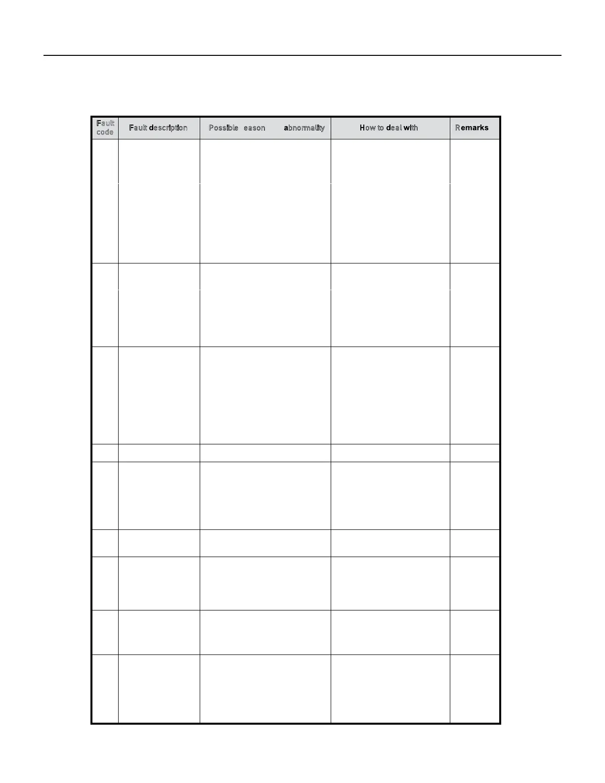
TROUBLESHOOTING
Outdoor Fault Code
Fault
code
Fault escription
Possible reasons for bnormality
RHow to eal ith
13
Compressor overheat
protector device
1. The wiring of the overload
protector is conne cted loose ly.
2. The overload protector fails .
3. The refrigerant is not enough;
4. The installation pipe is much
longer than the norma l one , but
extra refrigerant is not add ed ;
5. The expansi on valve fails;
6. The outdo or control board fails.
14
1.
2.
The high pressure
switch operation or
the unit is turned off
for high pressure
protection
fails;
1. Reconnect the wiring of the
overload protector;
2. Replace the overload
protector;
3. Check the welding point of the
unit to confirm whether it is
leakage, and then recharge
the refrigerant;
4. Add the refrigerant;
5. Replace expansion valve;
6. Replace the outdoor control
board.
The wiring of the high pressure
protector is conne cted loose ly;
The high pressure protector
1.
2.
3.The outdoor control board is
abnormal;
4. Overload in cooling;
5. Overload in heating.
Reco nnect the wiring of the
high pressure protector;
Replace the high pressure
protector;
Applied to
high
pressure
models with
switch or
pressure
sensor
3. Repl ace the outdo or control
board;
4. Please refer to NOTE 3;
5. Please refer to NOTE 4.
15
The low pressure
switch protection or
the unit is turned off
for low pressure
protection
1. The wiring of the low pressure
switch is connect ed loose ly;
2. The low pressure switch fails;
3. The refrigerant is not enough;
4. The expansi on valve fails in
heating mode;
5. The outdoor control board is
abnormal.
Applied to
models with
low pressure
switch or
pressure
sensor
16
O verload protec tion
in cooli ng mode
System overload
1. Recon nect the wiring of the
low pressu re switch;
2. Repl ace the low pressure
switch;
3. Check the welding point to
confirm whethe r the unit leaks ,
and add some refrigerant;
4. Repl ace the expansio n valve;
5. Repl ace the outdo or control
board.
Pleas e refer to NOTE 3.
17
Discharge
temperature sensor
fault
1.The wiring of the discharge
tempe -rature sensor is connect ed
loose ly;
2. The discharge temperature
sensor fails;
3.The sampling circuit is abnormal.
18
1. Reco nnect the wiring of the
discharge temperature sensor;
2. Replace the discharge
temperature sensor;
3. Replace the outdoor control
board.
AC voltage is
abnormal
1.The AC voltage>27 5V or <160V ;
2.The AC voltage of sampling circuit
on the driver board is abnormal .
19
1. Normal protection, please
check the supply power;
2. Repl ace the driver board.
Suction temperature
sensor fault
1.The wiring of the suction tempe -
rature sensor is connect ed loose ly;
2.The suction temperature sensor
fails;
3.The sampling circuit is abnormal .
22
The defrosting sensor
fault
1.Reconnect the wiring of the
suction temperature sensor;
2.Replace the suction
temperature sensor;
3.Replace the outdoor control
board.
1.The wiring of the defrosting sensor
is conn ected loose ly;
2.The defrosting sensor fails;
3.The sampling circuit is abnormal .
45 IPM fault
1. Reconnect the wiring of the
defrosting sensor;
2. Replace the def rosting sensor;
3. Replace the outdoor control
board.
See attached "analysis of the
driving board fault".
There are many reasons for this
failure. You can check the driver
board fault LED to further analyze
the fault code of the drive board and
to learn about what leads to the fault
and how to operate it . Specific
information can be seen in table 5,
table 6.
 Loading...