25 PB
OPERATION
Remote Thermostat Connection
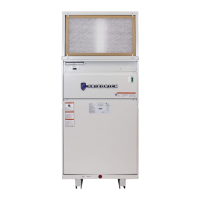
Remote Wall Thermostat Location
The thermostat should not be mounted where it may be affected by drafts, discharge
air from registers (hot or cold), or heat radiated from the sun appliances, windows
etc.. The thermostat should be located about 5 Ft. above the oor in an area of average
temperature, with good air circulation.
Thermostats should be level for aesthetics.
Note: An improperly operating or poorly located remote wall thermostat can be the
source of perceived equipment problems. A careful check of the thermostat’s location
and wiring must be made to ensure that it is not the source of problems.
Remote Thermostat
All Friedrich Vert-I-Pak units are configured to be controlled by using a dual stage heat/cool remote
wall mounted thermostat. The thermostat may be auto or manual changeover as long as the control
configuration matches that of the Vert-I-Pak unit.
To connect the wall mounted thermostat:
1. Pull the disconnect switch.
2. Unscrew and remove the control box panel.
3. Select which side to run your thermostat wire.
4. Run the wires through the side hole in the box to reach the connection terminal wiring.
5. Make the connections, appropriately matching the wires as shown in the wiring diagram.
6. Reattach the control box cover.
Figure 303 (Thermostat Locations)
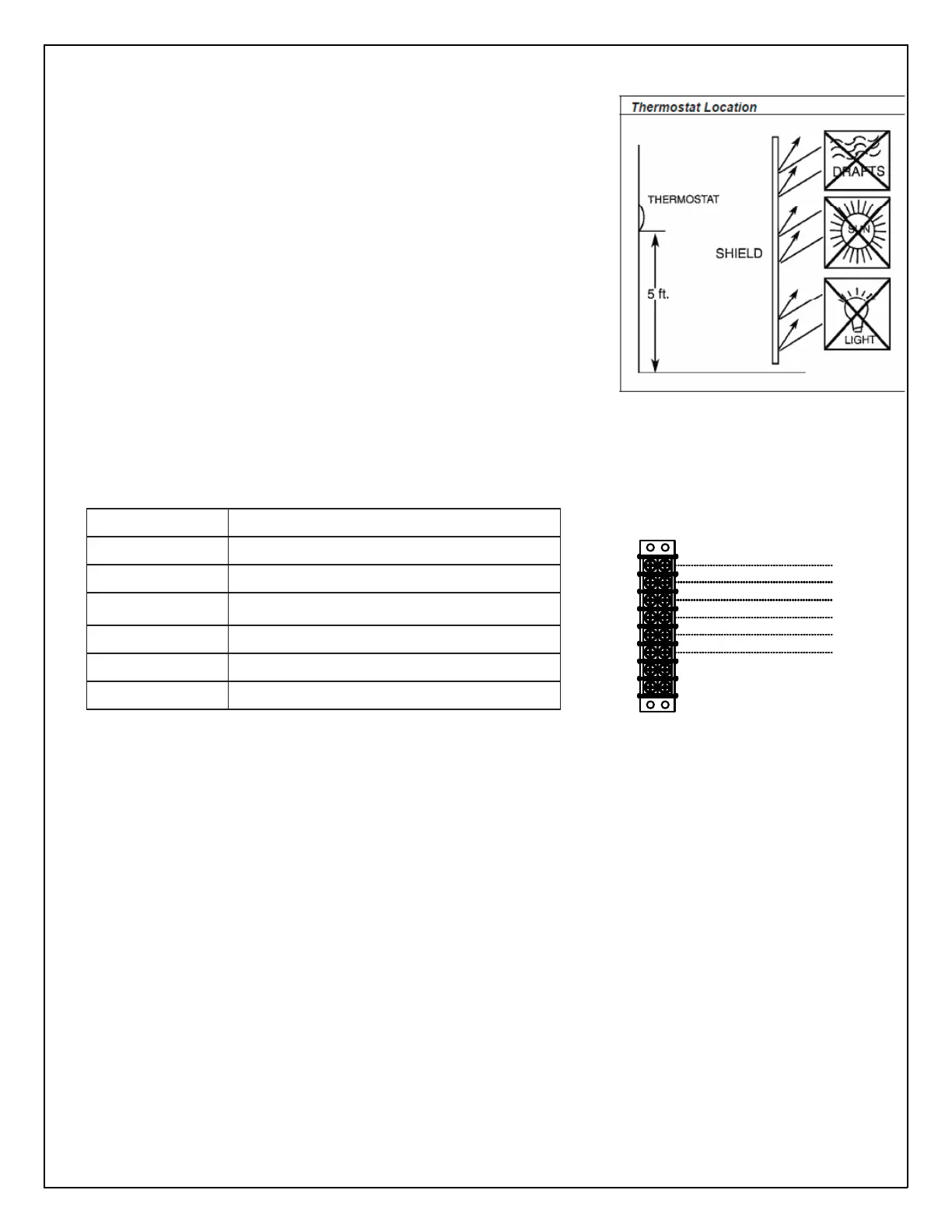
R
Y
G
B
W2
C
VPAK Low- Voltage Connections
Terminal Code Wire Connection Function
C Common Ground Terminal
G Call for Fan*
B Call for Heat Pump (Reversing Valve)
Y Call for Compressor
W2 Emergency Heat
R 24 VAC to Wall Thermostat
Note: It is the installer’s responsibility to ensure that all control wiring connections are made in accordance with the installation instructions.
Improper connection of the thermostat control wiring and/or tampering with the unit’s internal wiring can void the equipment warranty and
may result in property damage, personal injury, or death. Questions concerning proper connections to the unit should be directed to the factory
Note: Any non-Friedrich thermostat or low voltage device being powered by the Vert-I-Pak will need to be reviewed and
approved for use.
Figure 304 (Thermostat Connections)
Figure 305 Low Voltage Connections)
 Loading...