26
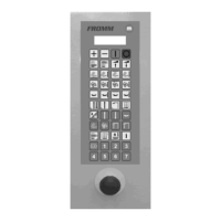
Carrello versione PS / MPS2
Con questa versione di carrello (Fig. 2.7 d) è possibile
regolare la tensione di applicazione del lm sul
bancale.
Questo carrello consente di prestirare il lm estensibile.
Il valore di prestiro è regolabile.
Il carrello è dotato di:
- un sensore (4), collegato al rullo di uscita, in grado di
rilevare la tensione del lm applicato sul bancale;
- due motoriduttori che trainano, tramite una
trasmissione ad ingranaggi, i rulli gommati (1), (2) e
(3);
- tre rulli folli con lo scopo di aumentare l’angolo di
avvolgimento del lm sui rulli gommati.
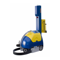
Una scheda elettronica specica, integra il segnale
del sensore (4) e la regolazione impostata tramite le
funzioni F13-16 nel pannello di controllo per controllare
dinamicamente la velocità del motore di traino dei rulli
di prestiro e quindi la tensione del lm.
Tramite le funzioni F17-20 si controlla la rotazione del
rullo (1) e (2). La differenza di velocità che si genera
tra i rulli gommati (1), (2) e (3) crea l’azione di prestiro.
All’avviamento occorre caricare il lm sul carrello come
segue:
Portare il carrello portabobina in posizione bassa per
facilitare l'inserimento della bobina.
Premere il pulsante di emergenza per arrestare la
macchina.
Inserire la bobina (7) sulla spina di centraggio (8).
Aprire il portello ed inserire il lm tra i rulli secondo il
percorso illustrato nello schema A, il simbolo con i trian-
goli identica il lato del lm su cui è applicato il collante
(se presente).
Lo schema A è una targa adesiva presente anche sul
carrello.
Richiudere il portello assicurandosi che le serrature siano
completamente inserite.
Riarmare il pulsante di emergenza per ripristinare la
macchina.
PS/MPS2 roll-holder carriage
With this carriage version (Fig. 2.7 d), the tension with
which the lm is applied to the pallet.. This carriage allows
pre-stretching the lm. The pre-stretch value is adjusted.
The carriage is tted with:
- a sensor (4), connected to the outfeed roller, which
measures the tension of the lm applied to the pallet;
- two gear motors which drive the rubber-coated roller
(1),(2) and (3) by means of toothed gearing;
- three idle rollers which are used to increase the winding
angle of the lm on the rubber-coated rollers.
A specic electronic circuit board integrates the signal
of the sensor (4) and the adjustment set using F13-16
functions in the control panel in order to dynamically
control the speed of the pre-stretch roller drive motor
and thus the lm tension.
Through the functions F17-20 controls the rotation of
the roller (1) and (2). The speed difference generated
between the rubber-coated rollers (1),(2) and (3) creates
the pre-stretch action.
Upon starting, the lm must be loaded onto the carriage
as follow.
Put the carriage into the Down position to make tting
the roll easier.
Press the emergency button to stop the machine.
Push the roll (7) onto the centre pin (8).
Open the door and insert the lm between the rollers
following the path indicated in gure A, the symbol with
the triangles identies the side of the lm to which the
bonding agent (if present) is applied.
Diagram A is an adhesive sticker also afxed to the
carriage.
Close the door making sure it is correctly secured.
Reset the emergency button to restart the machine.