EasyManua.ls Logo

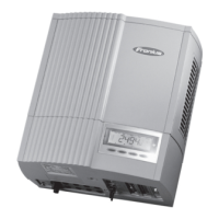
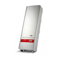
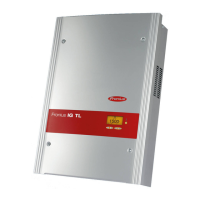
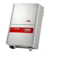
Fronius IG Plus 70 V-2 User Manual

Fronius IG Plus 70 V-2
168 pages
To Next Page IconTo Next Page
Page #1 background imageLoading...
Page #1 background image
42,0426,0062,EA 02/2011
Fronius IG Plus
30 V / 35 V / 50 V / 70 V
100 V / 120 V / 150 V
g
Operating Instructions
Inverter for grid-connected photo-
voltaic systems

Table of Contents

Question and Answer IconNeed help?

Do you have a question about the Fronius IG Plus 70 V-2 and is the answer not in the manual?

Fronius IG Plus 70 V-2 Specifications

General IconGeneral
BrandFronius
ModelIG Plus 70 V-2
CategoryInverter
LanguageEnglish

Summary

Safety Rules

Safety Rules Explanation

Explains the meaning of DANGER, WARNING, CAUTION, NOTE, and IMPORTANT safety indicators.

General Safety Guidelines

General safety principles for device operation, qualified personnel, and installation site.

General Information

Protection of Persons and Equipment

Safety features like galvanic isolation and grid monitoring for user and device protection.

Installation and Startup

Fronius IG Plus Installation and Connection

Details on installing and connecting the inverter to the PV system.

Choosing the Location

Criteria for selecting a suitable installation site for the inverter.

Fronius IG Plus Installation

Step-by-step guide for physically installing the inverter.

Connecting the Fronius IG Plus to the Public Grid (AC)

Connecting Solar Module Strings to the Fronius IG Plus (DC)

Ungrounded System: Connecting Solar Module Strings

Procedure for connecting solar module strings in an ungrounded system.

Solar Module Ground at Negative Pole: Connecting Solar Module Strings

Steps for grounding solar modules at the negative pole.

Solar Module Ground at Positive Pole: Connecting Solar Module Strings

Steps for grounding solar modules at the positive pole.

Data Communication and Solar Net

Commissioning

Start-up Operation

Steps and indicators for starting up the inverter.

Product Description Fronius IG Plus

Controls and Indicators

Identifies and describes the inverter's controls and status indicators.

Startup Phase and Grid Feed-in Mode

Startup Phase

Describes the inverter's self-test and grid synchronization process.

Operation of Feeding Energy into the Grid

Explains how the inverter feeds power into the grid and its status indicators.

The Setup Menu

Accessing the Setup Menu

Steps to navigate and enter the inverter's setup menu.

Menu Items in the Setup Menu

LIMIT CFG

Displays settings for utility company compliance (voltage/frequency limits).

Setup Lock Function

Activating/Deactivating the "Setup Lock" Function

Steps to enable or disable the setup lock using an access code.

Troubleshooting and Maintenance

Status Diagnosis and Troubleshooting

Overview of the inverter's self-diagnostic system and status codes.

Displaying Status Codes

Explains how status codes are displayed and what they indicate.

Class 1 Status Codes

Codes related to grid conditions, often temporary.

Class 4 Status Codes

Codes often requiring intervention from a trained service technician.

Class 5 Status Codes

Codes that generally do not impair feed-in operation, require acknowledgement.

Maintenance

Opening Fronius IG Plus for Service/Maintenance

Step-by-step procedure for safely opening the inverter for service.

Replacing String Fuses

Safety

Safety warnings and precautions before replacing fuses.

Replacing Fuses

Detailed instructions for replacing string fuses.

Related product manuals