34
Connecting the Fronius IG Plus to the Public Grid
(AC)
Monitoring the
Grid
Installations with
Several Inverters
For larger photovoltaic systems, it is possible to connect several inverters in parallel with-
out any problems. To ensure symmetrical feeding, connect the inverters uniformly to all 3
phases.
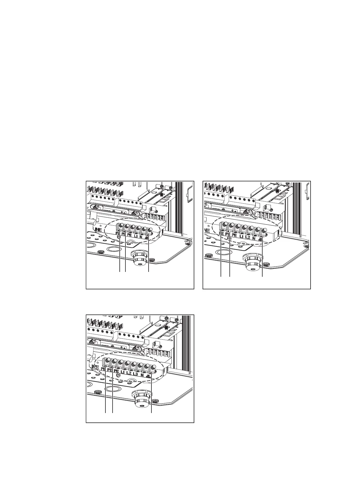
AC-Side Termi-
nals
IMPORTANT! The resistance in the leads to the AC-side connection terminals must be as
low as possible for optimal functioning of grid monitoring.
One-Phase Inverters Two-Phase Inverters
Three-Phase Inverters Legend:
L1 Phase conductor
L2 Phase conductor
L3 Phase conductor
PE PE conductor *)
N Neutral conductor
(a) Grounding electrode terminal *)
(b) Terminal for possible grounding of
the solar module frame
(c) "US Sense" terminal (for USA) *)
max. cable cross section 25 mm²
*) IMPORTANT: Only one PE con-
ductor terminal is available on the
Fronius IG Plus 100V-2.
(a)
(b)
(c)
(a)
(c)
(b)