18
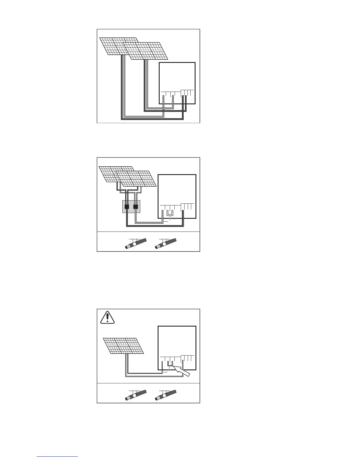
Connecting two solar module fields to an inverter with
multiple MPP trackers
Divide the strings between the two MPP tra-
cker inputs (DC+1/DC+2). The DC- termi-
nals can be used however you wish, as
they are internally connected.
When starting for the first time, set MPP
TRACKER 2 to "ON" (this can also be done
later in the Basic menu).
Single MPP tracker mode on an inverter with multiple MPP trackers:
Connecting multiple interconnected solar module
fields to an inverter with multiple MPP trackers using
one lead
If the strings are connected using a string
collection box and only one bus is used for
connection to the inverter, the connection
DC+1 (pin 2) and DC+2 (pin 1) must be
jumpered.
The cable cross-section of the DC connec-
tion lead and the jumpering must be the sa-
me. Jumpering of the DC terminal is not
necessary, as these terminals are jumpe-
red internally.
When starting for the first time, set MPP
TRACKER 2 to "OFF" (this can also be
done later in the Basic menu).
If the inverter with multiple MPP trackers is
operated in single MPP tracker mode, the
currents from the connected DC leads are
divided evenly across both inputs.
Single MPP tracker mode with only one string on an inverter with multiple MPP
trackers:
Connecting only one string to an inverter with multiple
MPP trackers
If only one string is used for connection to
the inverter, the connection DC+1 (pin 2)
and DC+2 (pin 1) must be jumpered.
The cable cross-section of the DC connec-
tion lead and the jumpering must be the sa-
me. Jumpering of the DC terminal is not
necessary, as these terminals are jumpe-
red internally.
When starting for the first time, set MPP
TRACKER 2 to "OFF" (this can also be
done later in the Basic menu).
If the inverter with multiple MPP trackers is
operated in single MPP tracker mode, the
currents from the connected DC leads are
divided evenly across both inputs.
DC-2
DC-
DC-1
max. 18 A
per MPPT
PV 1
PV 2
12
12
34
12
DC+1 DC+2
DC+1
DC+2
PV 1
PV 2
1
DC+1
DC-1
DC+2
DC-
1
1234
22
D1
D1
=
*
*
DC+1
max. 36 A to
a single
DC terminal
PV 1
1
DC+1
DC-1
DC+2
DC-
1
1234
22
D1
D1
=
*
DC+1
max. 36 A to
a single
DC terminal
WHEN ONLY ONE STRING IS USED
*