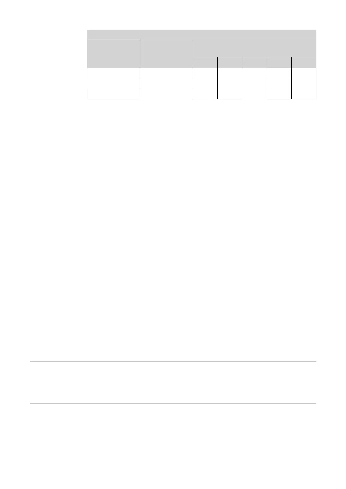
Line resistances at different cross-sections (copper wires)
Secondary cur-
rent
[A]
Cross-section
[mm²]
Line resistances at different lead lengths
(outgoing and return lead)
0.5 m 1.0 m 2.5 m 5 m 10 m
5 1.5 0.3 VA 0.6 VA 1.5 VA 2.9 VA 5.8 VA
5 2.5 0.2 VA 0.4 VA 0.9 VA 1.8 VA 3.6 VA
5 4 - - 0.6 VA 1.1 VA 2.2 VA
Example
The length of the outgoing and return lead (0.5 m each) between the Fronius Smart
Meter and the current transformer is a total of 1 m and has a copper cable cross-section
of 1.5 mm²; the line resistance is therefore 0.6 VA according to the table above. The self-
consumption of the Fronius Smart Meter is 0.3 VA.
Line resistance 0.6 VA + self-consumption 0.3 VA = 0.9 VA
→ A current transformer with a rating of 1 VA, 1.5 VA, 5 VA or higher is suitable here.
Accuracy class
Use Class 1 or better (Class 0.5, 0.2, etc.). Class 1 is equivalent to a deviation of ± 1% of
the secondary current at maximum power.
Mounting
Rigid or hinged.
"Rigid" is usually cheaper with better power and accuracy values. Hinged current trans-
formers can be opened for attachment to the conductor. To prevent it being opened inad-
vertently, a plastic cable tie can be secured to the current transformer. Hinged current
transformers can be installed in a system without interrupting the voltage.
Connecting the
current trans-
formers
- Make sure that the current transformers match the voltage phases.
Make sure that current transformer L1 measures the current on the same phase that
is monitored by voltage input L1. The same applies for phases L2 and L3.
- Make sure that the current transformers are pointing in the correct direction.
Observe the data sheet for the current transformer.
Attach the current transformers to the conductor to be measured and connect the current
transformer cables to the Fronius Smart Meter. Always switch off the power supply
before disconnecting live conductors.
The current transformers are connected to connections 1 and 3; 4 and 6; 7 and 9. If
necessary, excessively long cables can be shortened accordingly. Observe the sequence
in which the phases are connected. Accurate power measurement is only ensured if the
mains voltage phases match the current phases.
Suitable voltage
transformers
Suitable voltage transformers: Only voltage transformers with a voltage range from 210
to 440 V (phase - phase) may be used. The voltage transformers must be connected to
terminals 2, 5, 8 and 11 at the point of direct voltage measurement.
Connecting the
data communica-
tion cable to the
inverter
Fronius SnapINverter:
Connect the data communication connections of the Fronius Smart Meter to the Fronius
system monitoring in the inverter. Several Smart Meters can be installed in the system,
see chapter Multi-meter system - Fronius SnapINverter on page 17.
12