(c) Fronius International GmbH, 2020
4/19
2. INSTALLING AND ACTIVATING A FRONIUS SMART METER
2.1 Schematics and Wiring Requirements
/ Wiring between Fronius Smart meter and inverter should use a CAT5 or CAT6 cable.
Important: To be compliant with the AS3000 standards, it is recommended to have the CAT5/CAT6 cable
in a heat shrink tubing (probably 10mm) when it enters the switchboard part or alternatively use a 240V
rated CAT5/CAT6 cable (e.g. Clipsal CBUS cable).
/ Connection is a data line for Modbus RTU / RS485 using screw terminals on the meter
/ Maximum distance: 300 m (980 feet)
/ Use a single core per terminal connection between Fronius Smart Meter and the inverter. For D+ and D- use
the single cores from the same colour (e.g. D+ is orange/white, D- is orange)
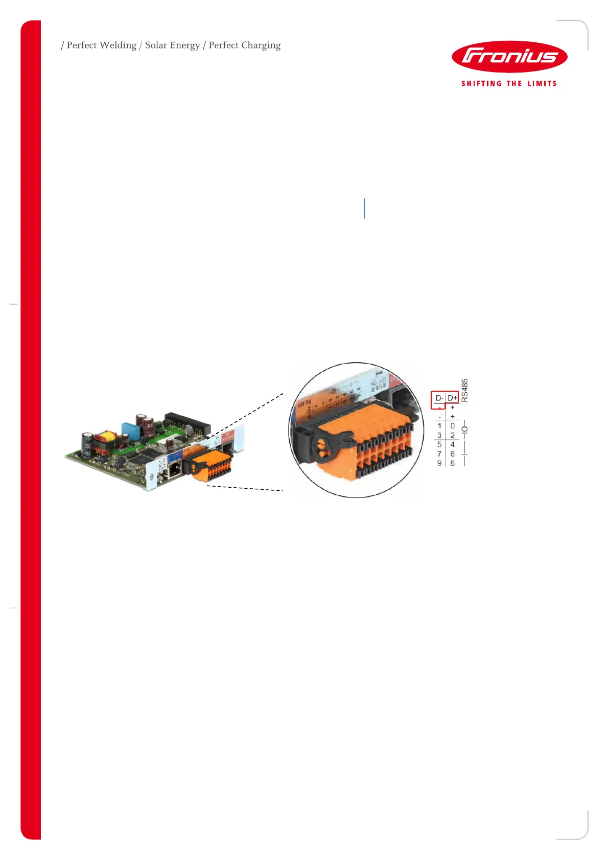
Meter connection on the Datamanager 2.0
The meter needs to be connected to the Datamanager’s terminal block using terminals D+, D- and -.

 Loading...


