15
EN
Carefully clean the oxide layer from the bare end of the cable by scraping it, e.g. with
a knife
IMPORTANT! Do not use brushes, files or emery paper, as the aluminium particles get
trapped and can be transferred to other conductors.
Once the oxide layer is removed, rub the end of the cable with a neutral grease, such
as non-acidic and non-alkaline Vaseline
Immediately connect the cable end to the terminal
IMPORTANT!Repeat the procedure if the cable has been disconnected and is to be re-
connected.
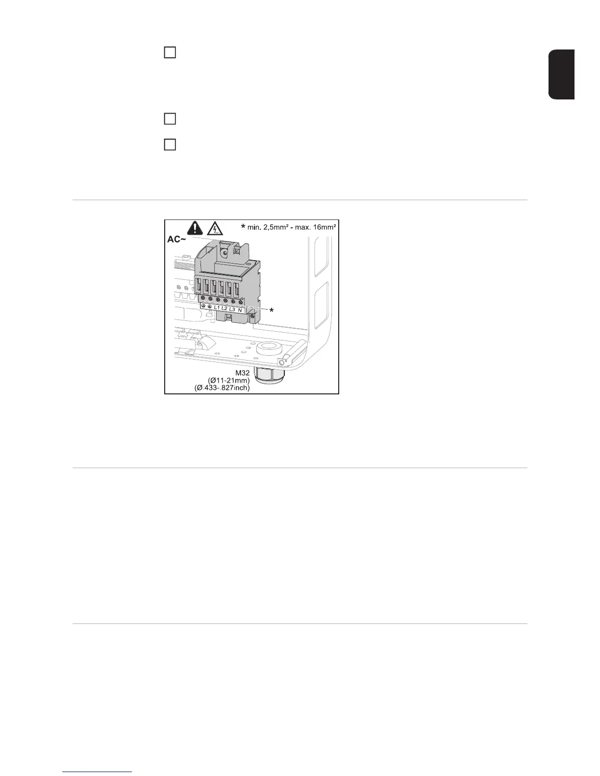
AC terminals
PE Ground conductor / grounding
L1-L3 Phase conductor
N Neutral conductor
Max. cross-section of each conductor cab-
le:
16 mm²
Min. cross-section of each conductor cable:
in accordance with the fuse rating on the
AC side, but at least 2.5 mm²
The AC cables can be connected to the AC
terminals without ferrules.
IMPORTANT! When using ferrules for AC cables with a cross-section of 16 mm², the fer-
rules must be crimped with a right-angled cross-section.
The use of ferrules with insulating collars is only permitted up to a max. cable cross-section
of 10 mm².
Cross section of
the AC cable
For a standard M32 metric screw joint with a reducer:
Cable diameter from 7-15 mm
When using an M32 metric screw joint (reducer removed):
cable diameter from 11-21 mm
(with a cable diameter of less than 11 mm, the strain-relief force is reduced from 100 N to
a maximum of 80 N)
With cable diameters greater than 21 mm, the M32 screw joint must be replaced by an M32
screw joint with a larger clamping area – item number: 42,0407,0780 – strain-relief device
M32 x 1.5 KB 18–25.
Connecting the
inverter to the
public grid (AC)
Note!
- Form loops with the AC cables when connecting them to the AC terminals.
- When securing the AC cables using a metric screw joint, ensure that the loops do not
protrude beyond the connection area.
Otherwise, under certain circumstances it may no longer be possible to close the inverter.
1
2
3
 Loading...


