20
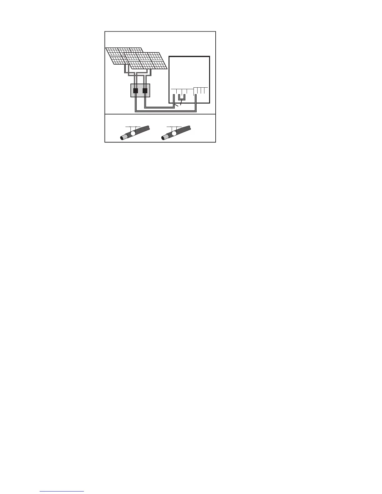
Connecting multiple interconnected solar module
fields to an inverter with multiple MPP trackers using
one lead
Single MPP tracker mode on an inverter
with multiple MPP trackers:
If the strings are connected using a string
combiner box and only one bus is used for
connection to the inverter, the connection
DC+1 (pin 2) and DC+2 (pin 1) must be
jumpered.
The wire diameter of the DC connection
lead and the jumpering must be the same.
Jumpering of the DC terminal is not neces-
sary, as these terminals are jumpered inter-
nally.
When starting for the first time, set MPP
TRACKER 2 to "OFF" (this can also be
done later in the Basic menu)
If the inverter with multiple MPP trackers is
operated in single MPP tracker mode, the
currents from the DC leads connected are
divided evenly across both inputs.
1
DC+1
DC-1
DC+1
DC+2
DC-
1
1234
22
PV 1
PV 2
D1
D1
=
*
*
Fronius Symo 3.0-3-M - 8.2-3-M
 Loading...


