17
EN
Wiring diagram variant 1: Signal contact for surge protection device
Depending on the setting in the Basic menu, the DC SPD option (surge protection device)
either outputs a warning or an error on the display. Further information on the DC SPD op-
tion can be found in the Installation Instructions.
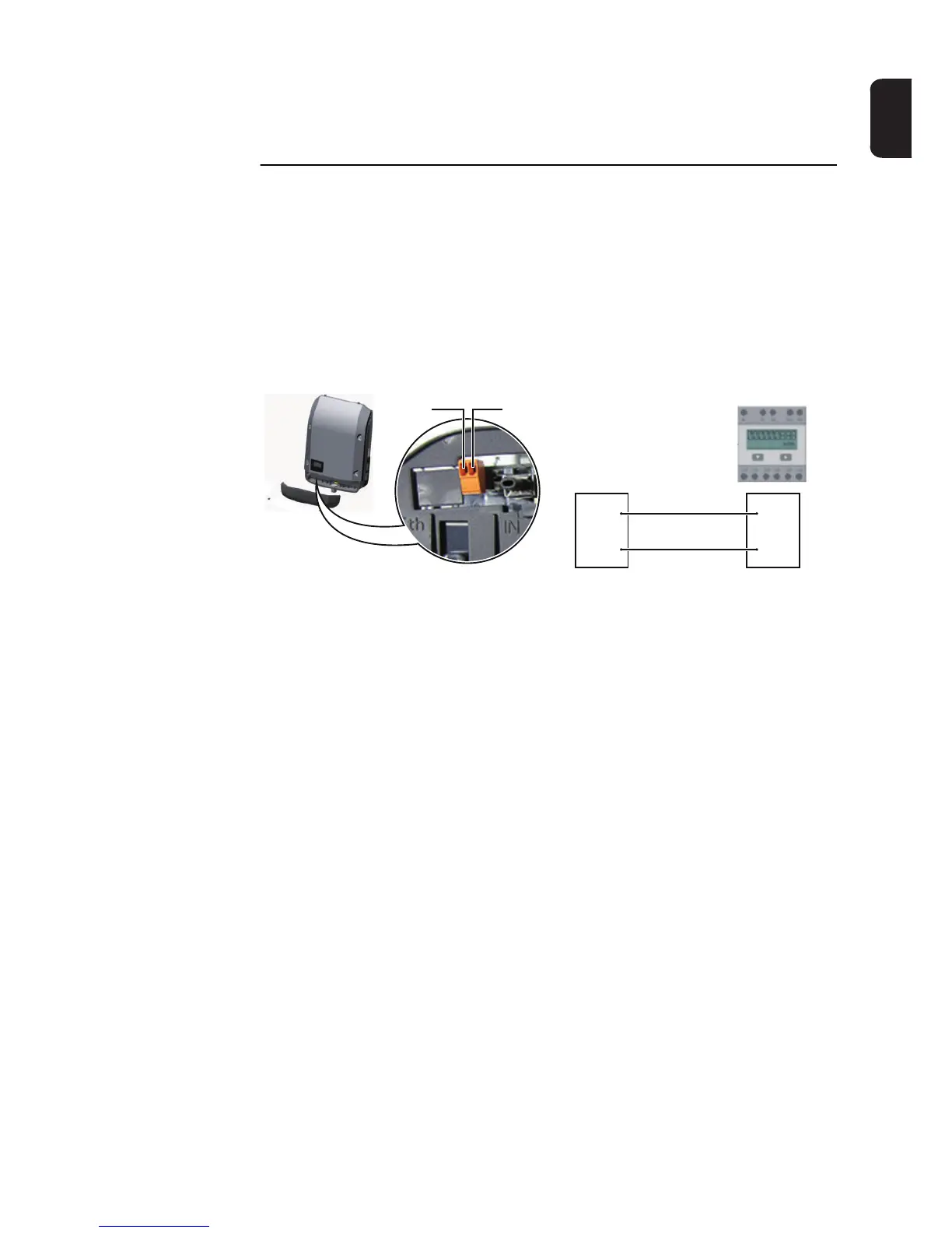
Wiring diagram variant 2: S0 meter
A meter for recording the self-consumption of each S0 can be connected directly to the in-
verter. This S0 meter can be positioned directly at the feed-in point or in the consumption
branch. As one of the settings on the Fronius Datamanager website, a dynamic power re-
duction can be set under the "EVU Editor" menu subitem (see Fronius Datamanager Op-
erating Instructions under
www.fronius.com/QR-link/4204260173DE)
IMPORTANT! In order to connect an S0 meter to the inverter, it may be necessary to up-
date the inverter firmware.
Requirements for the S0 meter:
- Must comply with the IEC62053-31 Class B standard
- Max. voltage 15 V DC
- Max. current when ON 15 mA
- Min. current when ON 2 mA
- Max. current when OFF 0.15 mA
Recommended max. pulse rate of the S0 meter:
PV output kWp [kW] Max. pulse rate per kWp
30 1000
20 2000
10 5000
≤ 5.5 10,000
Pin 1Pin 2
Pin 1
Pin 2 S0 +
S0 -
 Loading...


