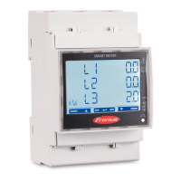
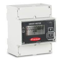
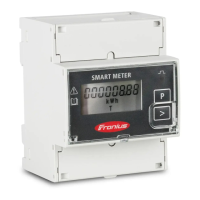
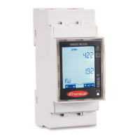
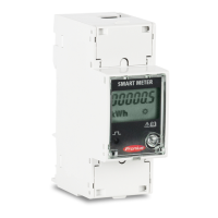
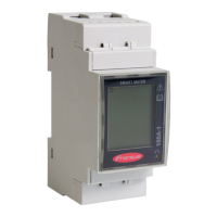
Three-Phase Two-Wire Corner Grounded Delta
Connect Current
Transformers
The current transformer must generate 333.33 millivolts AC at rated current.
See the current transformer data sheets for CT ratings (Fronius CT,
41,0010,0104 / 41,0010,0105 / 41,0010,0232 / 41,0010,0233).
-
Do not use ratio or current output such as 1 amp or 5 amp output models!
-
See the CT data sheets for the maximum input current ratings.
-
Be careful to match the CTs with the voltage phases. Make sure the CT L1 is
measuring the current on the same phase being monitored by the L1 voltage
input and the same for phases L2 and L3. Use the supplied colored labels or
colored tape to identify the CT leads.
-
To minimize current measurement noise, avoid extending the CT wires, espe-
cially in noisy environments. If it is necessary to extend the wires, use twisted
pair cable 22 to 14 AWG, rated for 300 V or 600 V (not less than the service
voltage) and shielded if possible
-
Make sure the CTs face the correct direction. An arrow might indicate either
the load or the source (public grid)
-
If you see strange readings on unused phases, jumper the unused CT inputs:
for each unused CT, connect a short cable from the terminal marked with a
white dot to the terminal marked with a black dot.
Install the CTs around the conductor to be measured and connect the CT leads
to the Fronius Smart Meter. Always turn off power before disconnecting any live
conductors. Put the line conductors through the CTs as shown in the previous
section.
CTs are directional. If they are mounted backwards or with their white and black
wires swapped the measured power will be negative. The status LEDs indicate
negative measured power by flashing red.
Split-core CTs can be opened for installation around the conductor. A nylon
cable tie may be secured around the CT to prevent inadvertent opening.
CT Wiring The current transformers connect to the six position black screw terminal block.
Connect the white and black CT wires to the Fronius Smart Meter terminals
marked CT L1, CT L2 and CT L3. Excess length may be trimmed from the wires if
desired. Connect each CT with the white wire aligned with the white dot on the
label and the black wire aligned with the black dot. Note the order in which the
13
EN-US
 Loading...
