phases are connected, as the line voltage phases must match the current phases
for accurate power measurement.
Connecting data
communication
cables to invert-
ers
Fronius SnapINveter:
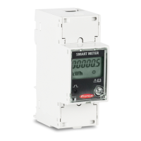
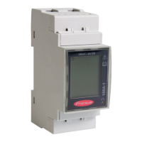
Connect the data communication ports of the Fronius Smart Meter to the Froni-
us system monitoring in the inverter. Several Smart Meters can be installed in the
system, see chapter Multi meter system - Fronius SnapINverter on page 19
1
Connect D- to D-.
2
Connect D+ to D+.
3
Connect - to -.
Fronius GEN24 inverter:
Connect the data communication ports of the Fronius Smart Meter to the Mod-
bus interface of the Fronius GEN24 inverter. Several Smart Meters can be in-
stalled in the system, see chapter Multi meter system - Fronius GEN24 inverter
on page 21
1
Connect D- to M1-.
2
Connect D+ to M1+.
3
Connect - to GND.
14
 Loading...
