Innovation · Expertise · Agility
4
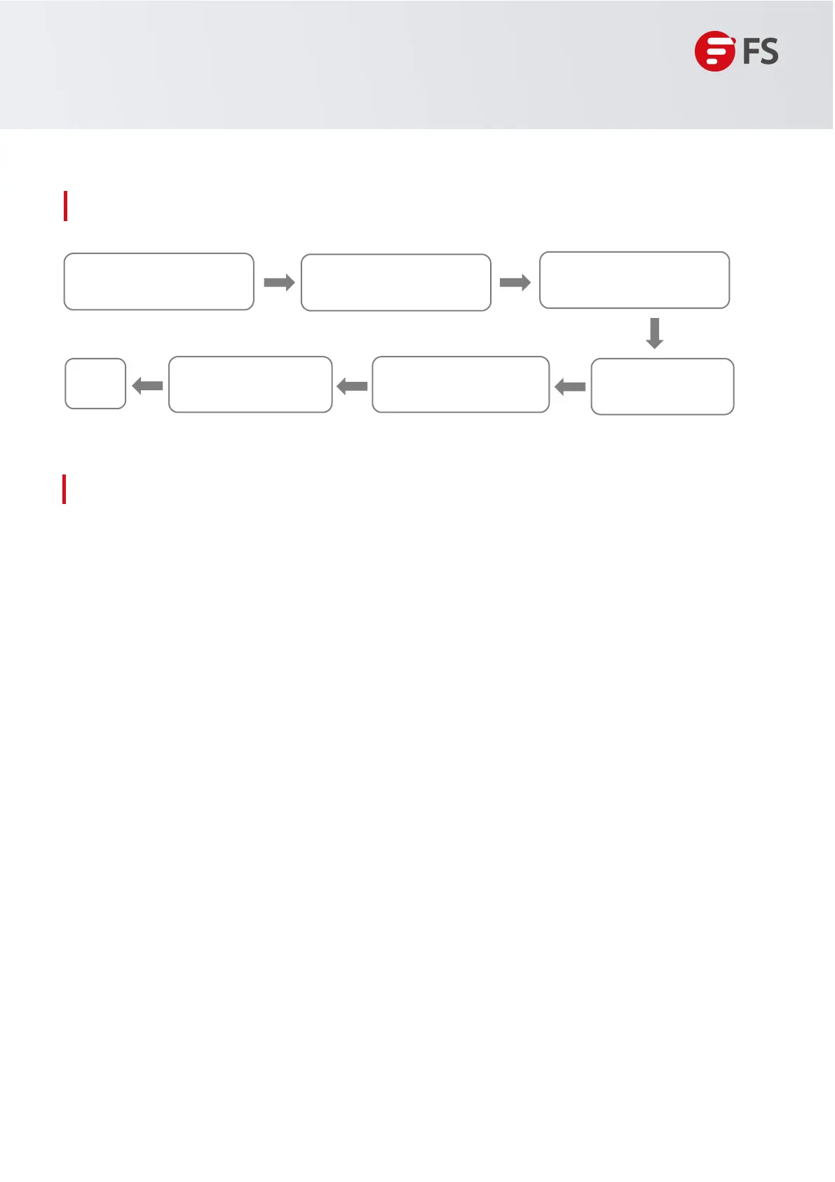
1.1 Installation Procedure
1.2 Installation Preparation
The S3410 switch is a relatively complex device, and the installation location, networking method, power
supply and alignment of the device should be carefully planned and arranged before installation.
Confirm the following before installation:
• The installation site provides sufficient space for heat dissipation.
• The installation site meets the temperature and humidity requirements of the switch.
• The power supply and required current are available in the installation site.
• The Ethernet cables have been deployed in the installation site.
1.2.1
Precautions
for
Safe
Use
Hardware
Installation
and
Parts
Replacement
Switch
Hardware
Installation
and
Maintenance
Guide
Installation Preparation
Connecting a SwitchPost-Installation Checks
System Commissioning
End
Installing a Switch
Installing Modules
During
installation,
note
the
following
points
• 100-meter network cables should be laid inside the equipment room and outdoor cabling of such cables is
prohibited.
If outdoor cabling is necessary, take relevant measures for lightning protection
• Connect the power cables of different colors to the corresponding grounding posts.
• Ensure that the interface of the power supply cable is properly connected to the power interface of the device
The power cablesmust be protected using power cable retention clips after they are connected to the device.
• Do not place any articles on the on the switch.
• Reserve a spacing of at least 10 cm around the chassis for good ventilation. Do not stackthe devices.
• The switch should be located at places free from the large power radio launch pad, radar launch pad, and
high-frequency
large-current
devices.
If
necessary,
use
electromagnetic
shielding.
For
example,use
interfac
cables to shield cables.
• 100-meter network cables should be laid inside the equipment room and outdoor cabling of such cables is
prohibited. If outdoor cabling is necessary, take relevant measures for lightning protection
 Loading...