Section 2 Functional Description
10 FT742-DM (RS485) Sensors – User Manual
2.2 Wind Speed Calibration
All FT742-DM wind sensors get calibrated in the FT production wind tunnel before dispatch. As the sensor has
no moving parts, there is no need to recalibrate a sensor over its lifetime as no measurement degradation will
occur. The sensor’s compact strong monolithic shape is designed to prevent accidental transducer movement
or damage. FT Technologies’ calibration procedure and wind tunnels are designed to give a calibration profile
that is within the accuracy limits set in the product technical specification (see Section 2.1). Periodically the
accuracy of FT’s wind tunnels are compared with the accuracy of an independent wind tunnel to ensure that no
drift has occurred.
In exceptional circumstances users may wish to apply additional calibration factors. The sensor has an option to
set a User Calibration Table, which can modify the wind sensor’s wind speed output (see Section 6.4.21).
The User Calibration Table can be programmed with up to 64 correction factors which are maintained in non-
volatile memory. When enabled, the uncorrected wind speed output is adjusted according to the stored User
Calibration Table records using linear interpolation. The adjustments are applied to wind speed readings
regardless of wind direction.
2.3 Wind Speed and Direction Filtering
It is important that the system does not rely exclusively on a single wind reading for any control decision. A
single reading may be inaccurate due to measurement error, turbulence, corruption or interference. It is
recommended that an average of wind readings is used. In addition if 100% data availability is required then a
second FT sensor or alternative wind sensors should be fitted in addition.
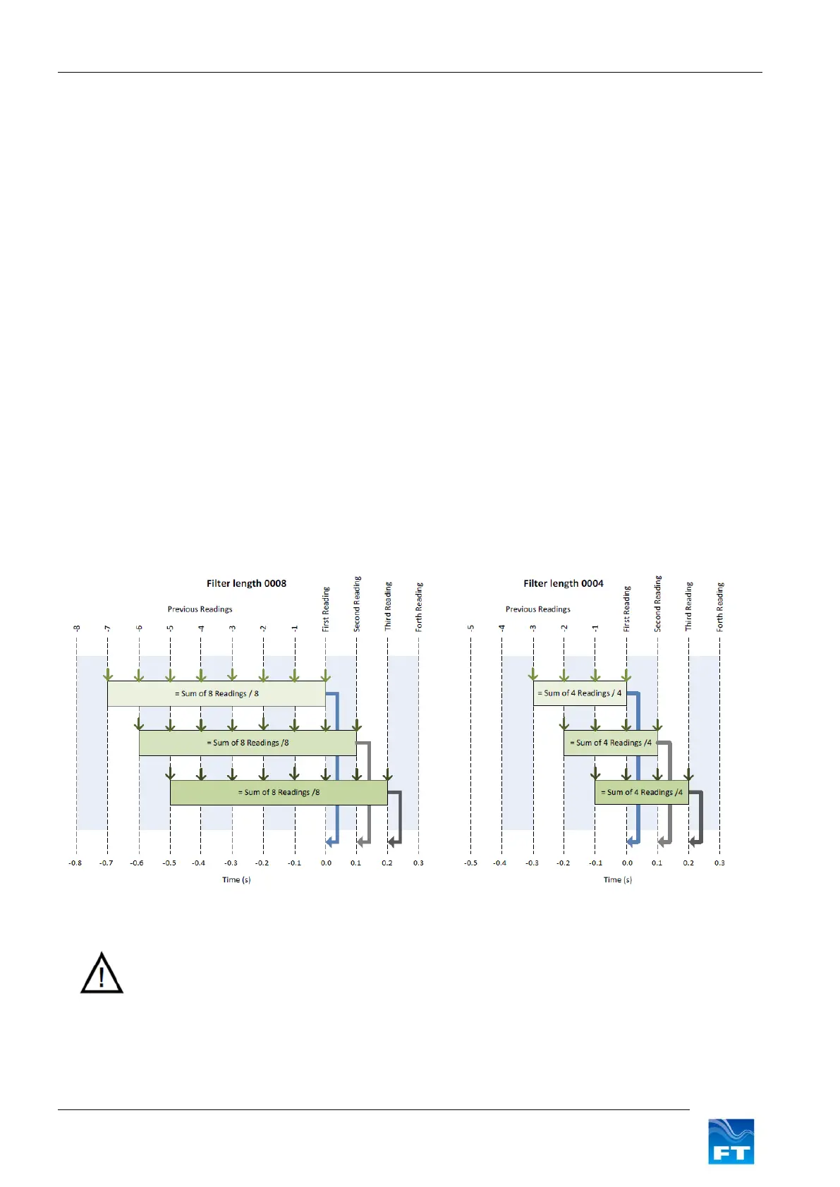
The sensor has optional internal filtering available. This is a digital finite impulse response (FIR) filter, which
works by calculating the moving average of a fixed number of previous readings. If filtering is being applied
externally, the sensor’s output filters can be disabled. If filtering inside the sensor is preferred, the length of the
averaging for both wind speed and direction can be independently set (see Sections 6.4.8 and 6.4.9).
Figure 2: Examples of FIR Filtering