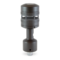
Section 2 Functional Description
12 FT742-DM (RS485) Sensors – User Manual
It is important to consider cable resistance losses and use a suitably rated cable of an appropriate length. FT
recommends cable types in Section 3.2 and the cable length should not exceed 15m. If longer cables runs are
required, consider the use of a junction box and heavy-gauge cable.
Since the heater circuit is thermostatically controlled, the actual power being drawn from the supply will depend
on the programmed set-point and the environmental conditions (i.e. ambient temperature, wind speed,
precipitation etc.). The maximum power that the sensor can consume is by default limited to 99W (4A with the
heater enabled). The power supply must be rated to provide the maximum power that the sensor can consume.
The maximum current limit of the sensor can be adjusted in software from 0.1 – 6A (from the default of 4A and
in increments of 0.1A). The current limit can be programmed at the factory, modified using the Acu-Test PC
software (see Section 4.4), or by using the software command (see Section 6.4.13). By default, the heater
requires a minimum of 11VDC for operation, see Section 6.4.13 for further details.
2.9 Low Power Operation
The sensor is designed for typical operation at 24VDC, however the sensor can operate below this (12-30VDC)
with reduced performance. By default, the heater will shut down at approximately 11VDC. Below approximately
8V the sensor may shut down. Lower voltages reduce the overall power consumption and heater performance.
For further advice on power and heater management strategies, see Sections 6.4.11, 6.4.12 and 6.4.13, or
contact FT Technologies.