Section 4 Service, Configuration & Testing
27 FT742-DM (RS485) Sensors – User Manual
4.4.2 FT054 Evaluation Cable
The digital sensors can be tested by connecting it to a computer. Figure 12 shows how the Evaluation Pack can
be quickly set up to evaluate the sensor using Acu Vis.
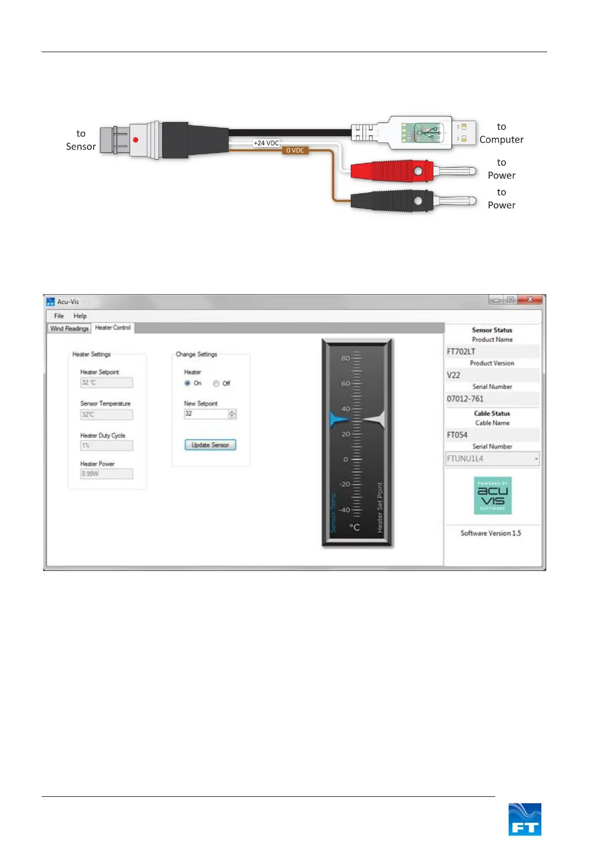
Figure 12: Electronic diagram
Warning: Live connection/disconnection of the power and/or sensors during live operation, or miswiring
of the power leads could damage the equipment and is not covered by FT’s standard warranty terms.
Figure 13: Acu-Vis Heater Controls
Heater Settings: Displays the Heater setpoint value (°C).
Sensor Temperature: Displays the actual reported temperature (inside the sensor).
Heater Duty Cycle: Displays the percentage of full scale power used by the heater.
Heater Power: Displays the dynamic power consumption of the heater.
Change Settings: Permits activation, deactivation and modification of the heater setpoint.