Section 5 Sensor Communication
29 FT742-DM (RS485) Sensors – User Manual
5 SENSOR COMMUNICATION
5.1 Introduction
The sensor features an easy to use ASCII-based communication protocol transmitted over an RS485 serial link.
The protocol incorporates checksum validation to ensure the integrity of all data transmissions. In addition to the
FT Technologies proprietary protocol the sensor can output the common NMEA 0183 MWV (Wind Speed and
Angle) sentence.
5.2 RS485 Protocol
The sensor is fitted with an RS485 half-duplex serial interface. Slew-rate limited drivers are used to reduce EMI,
and minimize reflections from improperly terminated transmission lines and stubs. The signal state definitions
for the serial interface data lines are as follows:
- The idle, marking, logical “1”, OFF or stop bit state is defined by a negative voltage on line A with
respect to line B.
- The active, spacing, logical “0”, ON or start bit state is defined by a positive voltage on line A with
respect to line B.
-
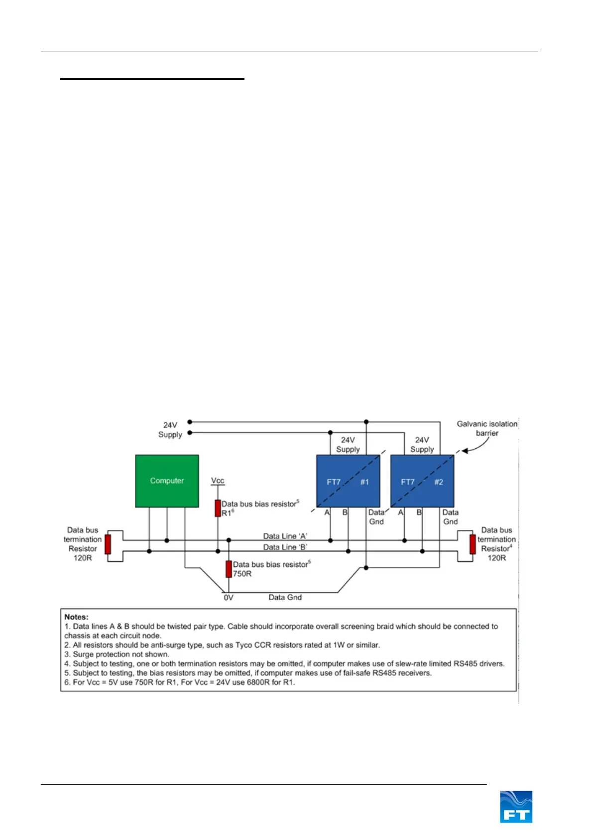
The circuit below (Figure 17) shows the recommended wiring diagram for connecting the sensor to the PC.
If two or more wind sensors are to be installed it is possible to use the same 2-wire data link to connect all the
sensor units to the computer.
Before using a sensor in a multi-device system, the Listener identifier of each sensor must be set to a unique
value. Use the ID command (Section 6.4.14) to set the Listener identifier for each sensor. If the Listener
identifiers are being set in the final host system, then it is important that only one sensor be connected at a time
to the RS485 bus until all devices have been assigned a unique Listener ID. Great care should be exercised
when using the ‘//’ characters for addressing. The ‘//’ address characters can be used to send a SET command
simultaneously to all sensor units (for example, to enable or disable filtering). Under no circumstances should
the ‘//’ characters be used with any QUERY commands since this will cause all sensor units to transmit data
resulting in bus contention.