Section 1 Introduction
7 FT742-DM (RS485) Sensors – User Manual
1 INTRODUCTION
1.1 Product Overview
The FT742-D-DM sensor is designed for general meteorological applications - particularly in harsh
environments such as areas of icing, sand, dust and offshore installation. The solid-state ultrasonic
wind sensor uses acoustic resonance airflow sensing techniques to measure both wind speed and
direction. The wind sensor has no moving parts to degrade or wear-out and is designed for
applications requiring high reliability.
Mounting and aligning the sensor is simple. A compass (not supplied) can be used to align the sensor
with magnetic North (0°) using the 0° wind datum marking feature (see Figure 3). For operation in ice-
prone areas, the FT742 is fitted with a highly-effective thermostatically controlled all-body heating
system. A three-element heater is used to ensure heat is evenly distributed over the entire surface
area.
FT sensors are configurable and can be factory programmed to the required customer settings,
contact FT Technologies for further details.
Note: The FT742-DM range is not suitable for turbine control applications. The FT742-FF and FT742-
PM ranges are designed for this application.
The standard FT742-DM, when installed to FT Technologies recommendations, is electrically isolated
from the mounting pole, making it unsuitable for conductively-grounded lightning protection schemes.
The addition of the FT035 grounding accessory provides a reliable, low-resistance grounding path.
Refer to Section 3 or contact FT Technologies for further information.
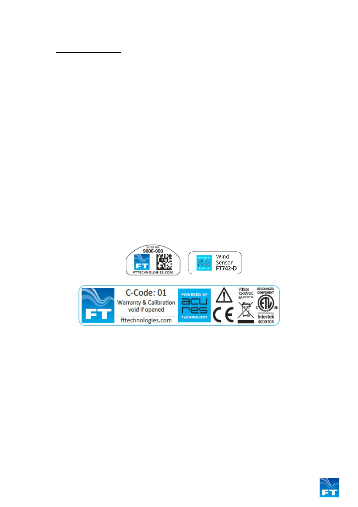
1.2 Build Versions and Labelling
Figure 1 shows how to identify a sensor, the serial number and calibration code (if applicable):
Additional labels may be attached. Only sensors marked with the Intertek label conform to the UL
Standard 61010-1 and are certified to CSA Standard C22.2 No. 61010-1.
Figure 1: Examples of Main Sensor Labels
1.3 Scope of Use
The sensor is designed, manufactured and optimised for high availability.
No promise in part or full can be given to guarantee a sensor’s continuous operation, as exceptional
circumstances can occur that may result in the failure of the output from a sensor. Exceptional
circumstances can include:
• Poor installation
• Inadequate inspection
• Power supply failures
• Poor quality electrical connections
• Lightning exposure
• Problematic environmental conditions or combination of conditions
• Physical Damage