Section 3 Mechanical & Electrical Installation
13 FT742-DM (RS485) Sensors – User Manual
3 MECHANICAL & ELECTRICAL INSTALLATION
The wind sensor has no moving parts to degrade or wear-out and is designed for applications requiring high
reliability and cold weather operation.
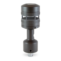
Figure 3: The Direct Mount Sensor
Direct Mount sensors are mounted vertically with the cable connector routed down through a 33.7mm (outer
diameter) hollow pipe (EN10255 standard sizes). 4 M6 screws can be used to secure the sensor onto the pipe
(Figure 7). The sensor body is manufactured from hard-anodised aluminium and the cavity has a water-repellent
coating.
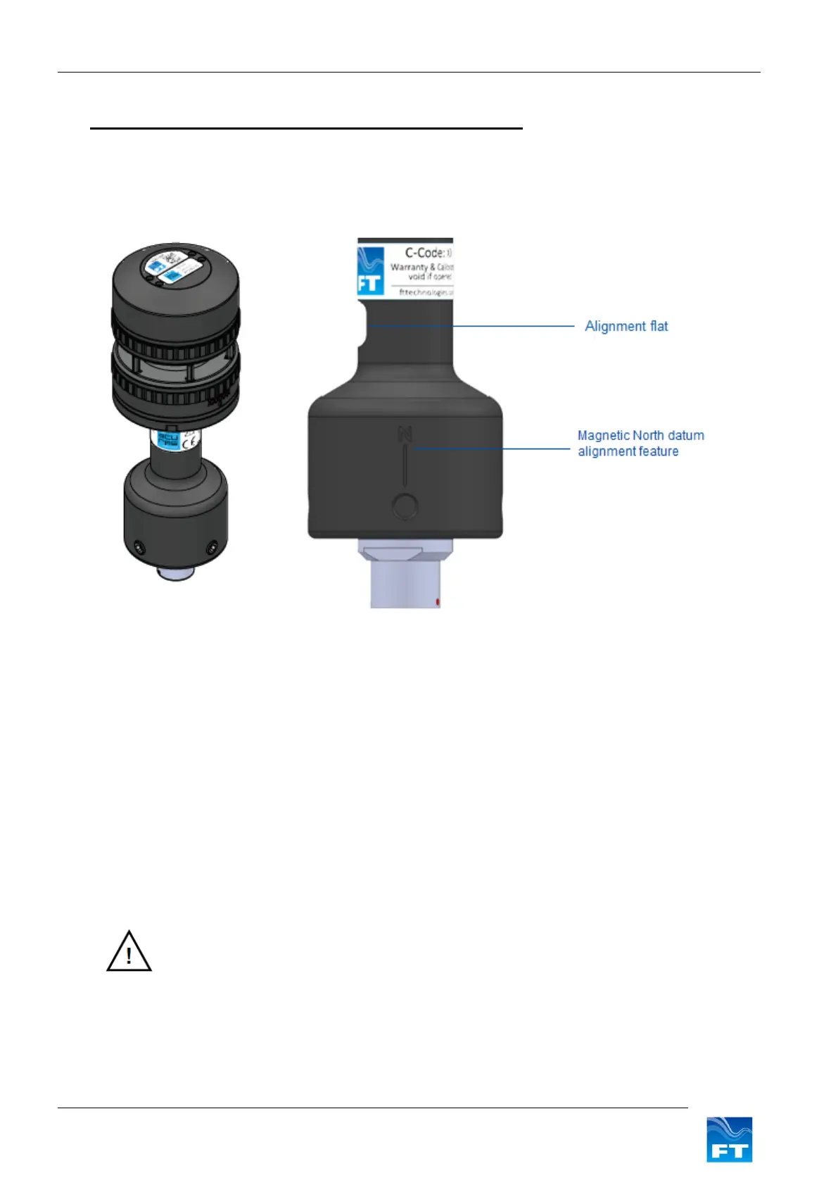
A suitable compass (not supplied) can be used to align the sensor with magnetic North using the convenient ‘N’
alignment marking and the alignment flat. The magnetic North marking indicates 0° and rotates clockwise when
viewed from above (see Figure 6). The alignment flat is used with a square-sided compass for rotational
alignment. Magnetic North should be lined up to face parallel to the ‘N’ marking feature.
Ensure the airflow into the sensor is not obstructed or influenced by nearby objects.
In order to keep the pressure within the sensor equalised with the atmospheric pressure, a small breather hole
is located within the connector housing compartment that should not be blocked.
• The wind sensor installation must be properly designed to ensure the correct
operation of the sensor. This section is for guidance only. It is the responsibility of
the designer and installer to ensure that the installation and its design is fit for
purpose. Please see Disclaimer Section 1.4.