43
WWW.FUHR.DE
multitronic
881/881GL/ServoAccess
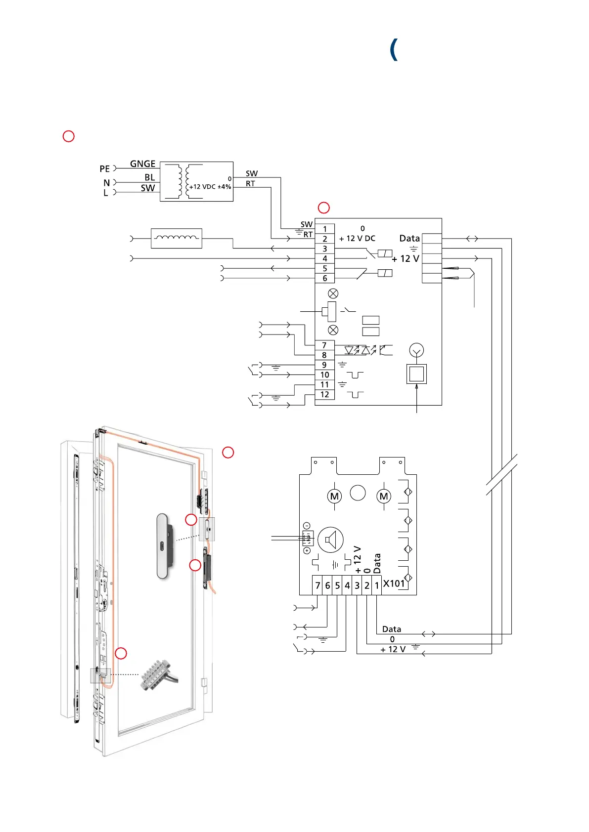
Main control unit
white
black (brown)
red (green)
Electricity and data transmission
Removable radio receiver
Terminal 16 & 17: Disconnection function of
access control systems by alarm system via
potential-free continuous signal
Tune-in button RADIO
DRT Jumper DRT
TGF Jumper TGF
13
14
15
16
17
Power supply via FUHR switching power supply unit
min. 12 V DC (residual ripple < 250 mVpp)
red (green)
black (brown)
white
Terminal 7-8: Input (6 ... 12 V AC or 6 ... 24 DC)
For opening impulse and day latch function 1.
Terminal 9-10: Input potential-free:
For opening impulse and day latch retaining
function. The swing door opener function 2 can
be activated by removing jumper DRT.
Terminal 11-12: Input potential-free:
For opening impulses and day-latch function 1.
The day-latch function 2 can be optionally
activated by removing jumper TGF.
2 V-Output for
external
indicator LED
Electrical swing door
opener (AC/DC)
Mains
(230 V AC)
Control unit in
the drive unit
3
2
1
Opening impulse
(potential-free)
GND
Opening impulse
6-12 V AC / 6-24 V DC
Output:
12 V DC (350 mA)
Alarm output
(opens if dry reed contact is open)
GREEN
RED
1
2
3
7 Wiring diagram