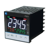
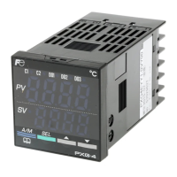
0RGHO6SHFL¿FDWLRQV
3;)3;)6WDQGDUGW\SH
Specifications
45678
PXF
4
5
6
7
8
9
10
11
12
13
5
9
A002
-
A
A
B
C
E
P
Y
A
C
E
P
R
S
2
0
1
F
M
J
Y
V
W
A
B
D
<Front panel size W × H>
48 × 96 mm
96 × 96 mm
–
<Control output 1>
Relay contact (SPST)
Relay contact (SPDT)
SSR drive output
Current output
Voltage output
<Control output 2>
None
Relay contact (SPST)
SSR drive output
Current output
Voltage output
Transfer output (current)
Transfer output (voltage)
<Revision code>
<Alarm output>
None
1 point
2 points
3 points
2 points (independent common)
<Power supply voltage/instruction manual>
100 to 240 V AC, Japanese & English
100 to 240 V AC, English
100 to 240 V AC, Chinese & English
24 V AC/DC, Japanese & English
24 V AC/DC, English
24 V AC/DC, Chinese & English
<Option>
None
RS-485 Communication
Digital input (DI1, DI2)
Remote SV input + Digital input (DI3)
CT input + Digital input (DI1)
RS-485 communication + Digital input (DI1)
RS-485 communication + Digital input (DI3, 4, 5)
+ Auxiliary alarm output (AL4, AL5)
–
9 10111213
Digit
Note
Note2
Note1
Y
M
T
H
G
V
C
0 0
Note 1: When using the CT input as a heater burnout alarm, add one alarm output for it. (Add one point in the 9th code.)
1RWH:KHQDFXUUHQWLQSXWLVXVHGDUHVLVWDQFHRIȍLVUHTXLUHGDWWKHLQSXWWHUPLQDO
- 22 -
 Loading...

