1
2
3
1
2
3
Point
:KHQWKHXVHUNH\IXQFWLRQFRGHLV691R3,'1RVHQGDQGWKHLQLWLDO3,'
1RDQG691RDUHGLIIHUHQWWKHILUVWWLPH\RXSUHVVWKHXVHUNH\3,'1RZLOOEHFRPHWKH
VDPHDV691R
$OVRWKH690;SDUDPHWHUYDOXHEHFRPHVWKHPD[LPXPVHOHFWDEOHQXPEHUIRU3,'1R
DQG691R
Ɣ6ZLWFK8VLQJ3DUDPHWHU³ ” via the Communication Channel
,QWKHFRPPXQLFDWLRQRYHUZULWHWKHVHWYDOXHWRWKHVHOHFWHG69QXPEHU
").
6WDUWXSPRGHIXQFWLRQ
7KHVWDUWXSPRGHVSHFL¿FDWLRQIXQFWLRQ VHWV WKHFRQWUROOHUWRVWDUWXSLQDQ\ RI DXWRPRGHPDQXDO
mode, remote mode or standby mode.
It is used when you want to start up in manual mode.
Use the following steps to set this function.
'LVSOD\WKHV\VWHPPHQX ")
'LVSOD\WKHVWDUWXSPRGH ") and choose the operational mode.
Choose from auto or manual.
Press the
key to set the value.
$IWHUFKDQJLQJWKHDERYHVHWWLQJUHVWDUWLQJWKHFRQWUROOHUZLOOVWDUWLWLQWKHVHOHFWHGPRGH
Point
When starting up in manual, the MV becomes 0%.
8VHUIXQFWLRQNH\
Pressing the NH\LQWKHSDUDPHWHUVFUHHQZLOOLPPHGLDWHO\UHWXUQ \RXWRWKH3969GLVSOD\
regardless of assigned function. Holding the
key, key + key, or key + key down for
DERXWDVHFRQGLQ3969GLVSOD\RU3909GLVSOD\ZLOOUXQWKHDVVLJQHGIXQFWLRQ
Refer to
For functions that can be assigned, see "12 USER key assignment" (page 21).
Use the following steps to set this function.
'LVSOD\WKHV\VWHPPHQX
")
'LVSOD\WKHDVVLJQXVHUNH\VSHFL¿FDWLRQ ") and choose the function.
Press the
key to set the value.
E$/DQG$UIXQFWLRQV
Ɣ7KHDQWLUHVHWZLQGXSIXQFWLRQ FXWV LQWHJUDWLRQ WKDWIDOOVRXWVLGHRIWKH$UVHWUDQJHWKDWLV
centered around SV.
5XQQLQJDXWRWXQLQJZLOOVHWWKHRSWLPXPYDOXHVIRU3LDQGGSDUDPHWHUVDVZHOODV$U
PV
SV
}
}
}
cuts integration
includes integration
cuts integration
PV
AR value
AR value
Ɣ7KHRXWSXWFRQYHUJHQFHYDOXHIXQFWLRQE$/RXWSXWVWR39DQG69DFDOFXODWHGUHVXOWRIWKH3,'
FRPSXWHG09SOXVWKHE$/RIIVHW
7KHIDFWRU\VHWWLQJRIE$/LVIRUVLQJOHRXWSXWIRUGXDORXWSXW
proportional
bandwidth
MV
bAL=40%
50%
PV
SV
40%
bAL=0%
100%
Point
$UWR$UDQGE$/WRE$/KDYHWKHVDPHIXQFWLRQDVLQHDFK3,'JURXS
10. MV limit functions
7KH09OLPLWIXQFWLRQDOORZV\RXWRFKRRVHZKHWKHUWROLPLWWKH09RUOHWLWSDVVWKURXJKPD[LPXP
and minimum MV.
PHC
PLC
103%
output value
(before limit)
PHC
PLC
limit
pass
limit
pass
–3%
output value
(after limit)
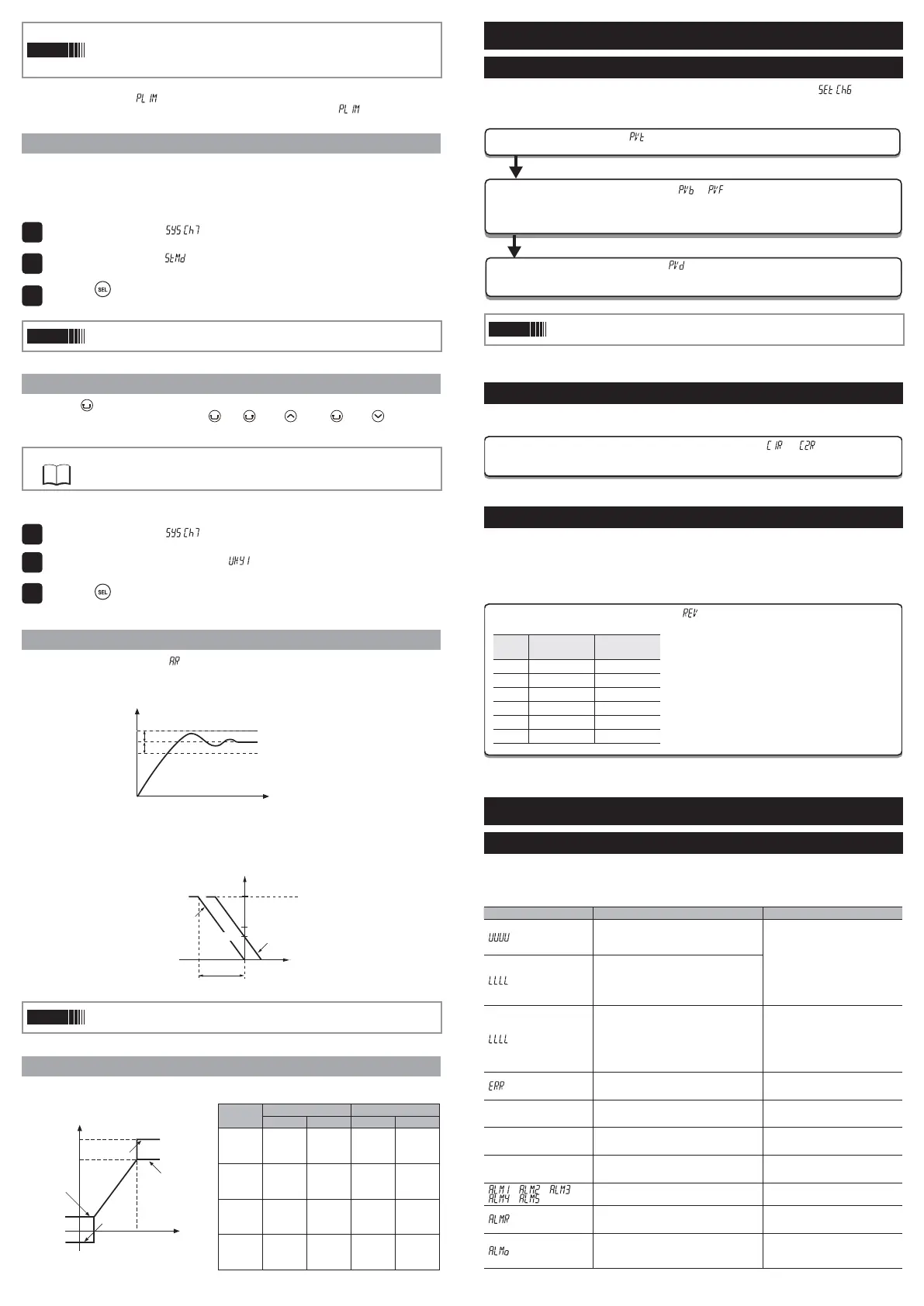
6HWWLQJWKH7HPSHUDWXUH&RQWUROOHU
,QSXW6HWWLQJ
Se
t the type and the range for input sensor. Input can be set in the setup menu ("
"].
For more on input types, input scaling, decimal point location, and input codes, see "10 Input Range
and Codes (standard range)". (page 19)
1. Choose an input type (" ")
Check the type of the thermocouple or resistance bulb which is used.
2. Set the PV scaling (input range) (" "/" ")
Set Pvb to the lower limit of the temperature range and PvF to the upper limit. It is recommended
to set the values at the standard range, even though they can be set at values beyond of it.
There is no standard range for DC voltage or DC current input. (-1999 to 9999, lower limit<upper limit)
3. Set the decimal point location (" ")
Sets whether or not to display digits after the decimal point. Two digits can also be dis-
played after the decimal point when using 1 to 5V DC, and 4 to 20mA DC.
Point
PV scaling and decimal point location can be used with the factory settings.
2XWSXW6HWWLQJ
Sets the control output. (Only when the output is current or voltage.)
1. Sets the range of the control output (OUT1, OUT2) (" " ")"
Choose any of 0 to 5V, 1 to 5V, 0 to 10V, 2 to 10V, 0 to 20mA or 4 to 20mA DC.
8-3. Control Setting
Sets controls to normal operation or reverse operation.
Ɣ5HYHUVHRSHUDWLRQ$VWKHSURFHVVYDOXH39ULVHVWKHFRQWURORXWSXW09EHFRPHVVPDOOHU8VHG
to heat the control object.
Ɣ1RUPDORSHUDWLRQ$VWKHSURFHVVYDOXH39ULVHVWKHFRQWURORXWSXW09EHFRPHVODUJHU8VHGWR
cool the control object.
1. Set the normal or reverse operation (" ")
Choose any of the following combinations of heat and cool to suit your system.
rEv
Control
output 1
Control
output 2
rv-- Reverse –
no-- Normal –
rvno Reverse Normal
norv Normal Reverse
rvrv Reverse Reverse
nono Normal Normal
(UURU,QGLFDWLRQV
'LVSOD\'XULQJ(TXLSPHQW(UURU
This controller has a display function to indicate several types of error code shown below. If any of the
HUURUFRGHLVGLVSOD\HGSOHDVHHOLPLQDWHWKHFDXVHRIHUURULPPHGLDWHO\$IWHUWKHFDXVHLVHOLPLQDWHG
turn off the power once, and then re-start the controller.
'LVSOD\ Possible cause Control output
"
"
(1) Thermocouple burnout.
5HVLVWDQFHEXOEVHQVRU$EXUQRXW
39H[FHHGVXSSHUOLPLWRIWKHUDQJHE\
5%FS.
Output as setting value when an error
occurs (set in parameter Flo1 or
Flo2)
"
"
(1) Resistance bulb sensor B or C wire burnout.
5HVLVWDQFHEXOEVHQVRUEHWZHHQ$%RU$
&VKRUW
(3) PV is below lower limit of the range by
5%FS.
%XUQRXWRUVKRUWLQWKHYROWDJHLQSXW
"
"
39
Control operation is continued
1RWH&RQWURORSHUDWLRQLVFRQWLQXHG
as long as the accuracy is above
-5%FS.
When the accuracy declines
to be lower than -5%FS, the
controller outputs the specified
value for an error.
" 69ÀLFNHUV
,QFRUUHFWVHWWLQJ3YE3Y)
The controller outputs the specified
value for an error. (The value can be
set in parameter Flo1 or Flo2)
PV is not displayed &KHFNWKHVHWYDOXHRI'637
1RUPDOFRQWURO
* The controller does not have to be
restarted
SV is not displayed &KHFNWKHVHWYDOXHRI'637
1RUPDOFRQWURO
* The controller does not have to be
restarted
Parameters may not be
displayed
&KHFNWKHVHWWLQJVRI&K'63
1RUPDOFRQWURO
* The controller does not have to be
restarted
"
", " ", " ",
" ", " "
$ODUPWR$ODUPLVRFFXUUHGXQGHUWKH
FRQGLWLRQWKDW$/0)LVVHWWRRU
1RUPDOFRQWURO
"
"
The number that relay has operated reached
WKH5<&1UHOD\FRQWDFWOLIH OLPLW XQGHU WKH
FRQGLWLRQWKDW$/0)LVVHWWRRU
1RUPDOFRQWURO
"
"
The number of days that the device has
operated reached the oPtM (upper limit of
RSHUDWLQJGD\VXQGHUWKHFRQGLWLRQWKDW$/0)
is set to 1 or 3.
1RUPDOFRQWURO
PCUT
MV1 MV2
PHC1 3/& PHC2 3/&
"0"
"1"
"2"
"3"
103%
103%
limit
limit
-3%
limit
-3%
limit
103%
103%
103%
103%
-3%
-3%
-3%
-3%
"5"
"6"
103%
103%
limit
limit
-3%
limit
-3%
limit
103%
103%
103%
103%
limit
limit
limit
limit
"9"
"10"
"11"
103%
103%
limit
limit
-3%
limit
-3%
limit
limit
limit
limit
limit
-3%
-3%
-3%
-3%
"12"
"13"
"15"
103%
103%
limit
limit
-3%
limit
-3%
limit
limit
limit
limit
limit
limit
limit
limit
limit
 Loading...


