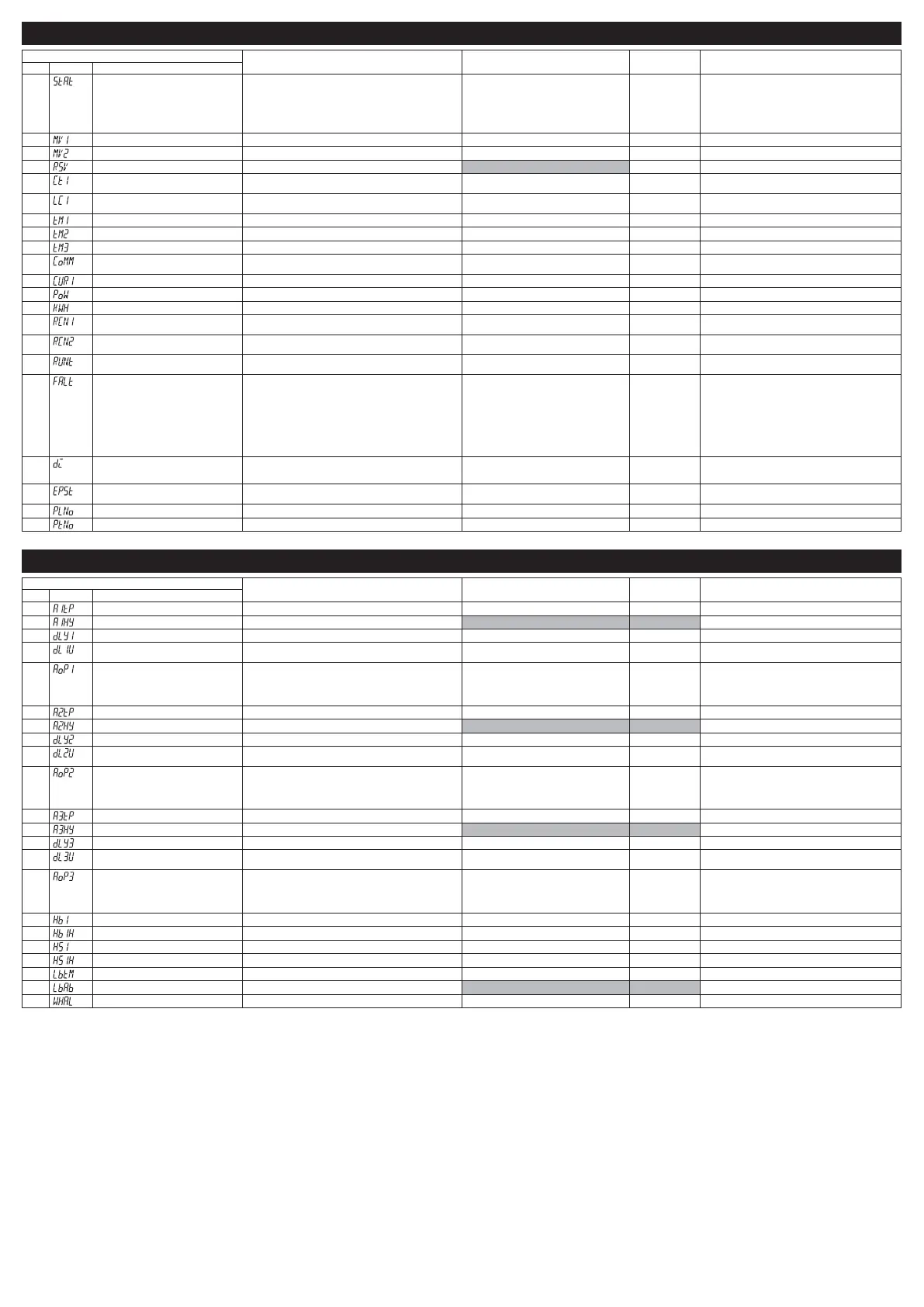
&K021PRQLWRUSDUDPHWHUV
3DUDPHWHU
)XQFWLRQ 6HWWLQJUDQJH ,QLWLDOYDOXH 5HPDUNV
ʋ 'LVSOD\ 1DPH
420
Ramp soak progress Displays the progress of the ramp soak oFF (ramp soak stopped)
1-rP (ramp in step 1)
1-Sk (soak in step 1)
64rP (ramp in step 64)
64Sk (soak in step 64)
(QGUDPSVRDN¿QLVKHG
—
421
MV1(%) Displays the output value of the control output (OUT1) -5.0 to 105.0% —
422
MV2(%) Displays the output value of the control output (OUT2) -5.0 to 105.0% —
424 Remote SV 6KRZVDUHPRWH69 -5% to 105%FS —
425 Heater current (A) 6KRZVDKHDWHUFXUUHQWYDOXH
$FXUUHQWYDOXHZKHQ287LV21
0 to 110.0 A —
427 SSR leak current (A) 6KRZVDOHDNFXUUHQWYDOXH
$FXUUHQWYDOXHZKHQ287LV2))
0 to 110.0 A —
429 Remaining time on timer 1 Displays the remaining time on timer 1 0 to 9999 sec/ 0 to 9999 min —
430
Remaining time on timer 2 Displays the remaining time on timer 2 0 to 9999 sec/ 0 to 9999 min —
431
Remaining time on timer 3 Displays the remaining time on timer 3 0 to 9999 s/0 to 9999 min —
435
Communication status Displays the communication status. 0 to 9999 times (number of communication
times)
—
436
Current (A) 6KRZVDYDOXHPHDVXUHGE\&7 0 to 110.0 A —
438 (OHFWULFSRZHU 6KRZVDFDOFXODWHGYDOXHIRUHOHFWULFSRZHU 0.0 to 9999 KW —
439 3RZHU 'LVSOD\VWKHFDOFXODWHGDPRXQWRIHOHFWULFSRZHU 0.0 to 999.9 Wh —
440 Number of opetating times (control relay
1)
Displayes the number of times that control relay 1 has
operated.
0 to 9999k times —
441 Number of opetating times (control relay
2)
Displayes the number of times that control relay 2 has
operated.
0 to 9999k times —
442 Operating days Displays the number of days oparated, converted from total
operating time.
0 to 5000 days —
443
Error source Displays the source of an error ELW39LQSXWXQGHUÀRZ////
ELW39LQSXWRYHUÀRZ8888
2 bit: PV underrange
3 bit: PV overrange
4 bit: R-SV underrange
5 bit: R-SV overrange
6 bit: Range setting error
8 bit: PV input circuit error
9 bit: R-SV input circuit error
10 bit: CT input circuit error
—
444
DI input state Displays the state of DI. 0 bit DI1
1 bit DI2
2 bit DI3
—
445
Communication error station number 6KRZVWKHVWDWLRQQXPEHUXQGHUDFRRSHUDWLYH
communication error or a programless communication error.
1 to 31 —
446
Current palette No. Displays the PID palette No. currently selected. 0-7 —
447 Current pattern No. Displays the pattern No. of the ramp soak currently selected. 0-15 —
&K$/0DODUPSDUDPHWHUV
3DUDPHWHU
)XQFWLRQ 6HWWLQJUDQJH ,QLWLDOYDOXH 5HPDUNV
ʋ 'LVSOD\ 1DPH
470 $/0DODUPW\SH 6HWWKHDODUPW\SHIRU$/0 0 to 58 0 Refer to section 11 for the detail.
471 $/0K\VWHUHVLV Sets the hysteresis for alarm output 1 ON/OFF 0 to 50%FS 0.25%FS
472 $/0GHOD\ Sets the delay before detecting alarm output 1 0 to 9999 [sec/min] 0
473 $/0GHOD\WLPHXQLWV Sets the delay time units for alarm output 1 sec (second)
Min (minute)
sec
474 $/0RSWLRQ $VVLJQVWKHRSWLRQDOIXQFWLRQVWR$/0
Ones digit: alarm output latch
Tens digit: error alarm
Hundreds digit: inverted output
Thousands digit: hold reset
0000 to 1111 0000
475 $/0DODUPW\SH 6HWWKHDODUPW\SHIRU$/0 0 to 58 0 Refer to section 11 for the detail.
476 $/0K\VWHUHVLV Sets the hysteresis for alarm output 2 ON/OFF 0 to 50%FS 0.25%FS
477
$/0GHOD\ Sets the delay before detecting alarm output 2 0 to 9999 [sec/min] 0
478
$/0GHOD\WLPHXQLWV Sets the delay time units for alarm output 2 sec (second)
Min (minute)
sec
479 $/0RSWLRQ $VVLJQVWKHRSWLRQDOIXQFWLRQVWR$/0
Ones digit: alarm latch bit mask
Tens digit: error alarm bit mask
Hundreds digit: inverted output bit mask
Thousands digit: hold reset bit mask
0000 to 1111 0000
480 $/0DODUPW\SH 6HWWKHDODUPW\SHIRU$/0 0 to 58 0 Refer to Section 11 for the detail.
481 $/0K\VWHUHVLV 6HWVWKHK\VWHUHVLVZLGWKIRUWKH212))FRQWURO 0 to 50%FS 0.25%FS
482 $/0GHOD\ Sets the delay before detecting alarm output 3 0 to 9999 [sec/min] 0
483 $/0GHOD\WLPHXQLWV Sets the delay time unit for alarm output 3 sec (second)
Min (minute)
sec
484 $/0RSWLRQ $VVLJQVWKHRSWLRQDOIXQFWLRQVWR$/0
Ones digit: alarm output latch
Tens digit: error alarm
Hundreds digit: inverted output
Thousands digit: hold reset
0000 to 1111 0000
500 HB alarm set value Sets the value to activate the heater burnout alarm. 0.0 to 100.0 (A) 0.0A
501
HB alarm hysteresis Sets an ON/OFF hysteresis for the heater burnout alarm. 0.0 to 100.0 (A) 0.5A
502
Shorted-load alarm set value Sets the alarm value for heater shorted load. 0.0 to 100.0 (A) 0.0A
503 Shorted-load alarm hysteresis Sets an ON/OFF hysteresis for the heater shorted-load alarm. 0.0 to 100.0 (A) 0.5A
508
/RRSEUHDNGHWHFWLRQWLPH Sets the time before detecting a broken loop 0 to 9999 sec 0 (Off)
509
/RRSEUHDNGHWHFWLRQUDQJH& Sets the temperature range before detecting a broken loop 0.0 to 100.0%FS 2.50%FS
511 Electricity alarm Sets the value for electricity alarm. 0-9999KWh 0
- 10 -

 Loading...