Mechanics
A26361-D1218-Z180-1-7619 English - 9
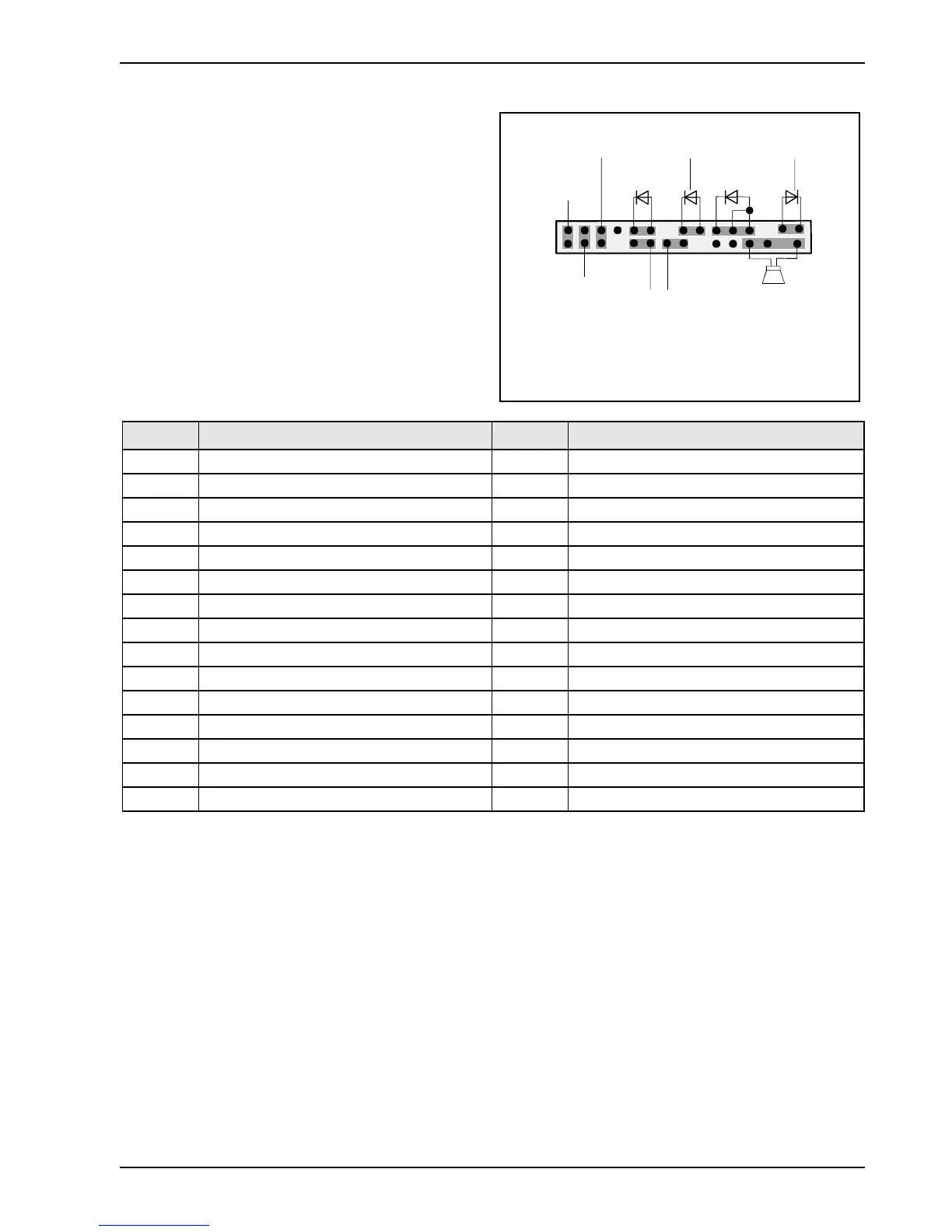
Front panel connector
1) Cable is not included in the delivery scope.
2) The same interface
3) 2pin or 3pin connector possible
1
2
HD-LED
1)
Power On/Off
SCSI LED Input
2)1)
Message LED
1)
Speaker
2)
1)
Sleep
Reset
1)
Power On
LED
1) 3)
Sleep LED
Pin Signal Pin Signal
1 Sleep LED (Cathode) 2 Speaker
3 Sleep LED (Anode) 4 Key
5 Key 6 GND
7 PowerON_LED (Anode) 8
1)
VCC or GND
9 PowerON_LED (Anode) 10 Key pin
11 PowerON_LED (Cathode) 12 Key pin
13 Message LED (Anode) 14 Key
15 Message LED (Cathode) 16 Not connected
17 Key 18 SCSI LED input (low asserted)
19 HD_LED (Anode) 20 SCSI LED input (low asserted)
21 HD_LED (Cathode) 22 Not connected
23 GND 24 Key
25 Power button (low asserted) 26 GND
27
2)
reserved 28 GND
29 Reset button (low asserted) 30 GND
1) Pin 8 is connected to VCC if audio is not onboard.
Pin 8 is connected to GND if audio is onboard.
2) The sleep button (optional) functions only for operating systems with APM (not with ACPI).