- 234 -
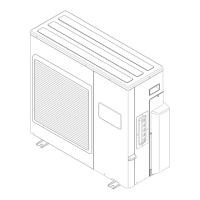
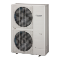
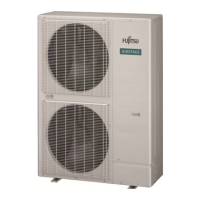
OUTDOOR UNIT
AOU36RLXFZH
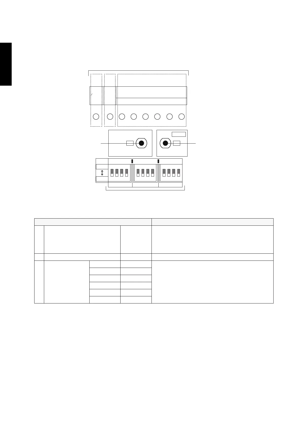
Setting method
1. Be sure to disconnect the power supply or turn off the breaker.
2. Change the DIP switch setting according to the required setting.
• Various settings can be adjusted by changing DIP switches and push switches on the
board of the outdoor unit.
• The printed characters for the LED display are shown below.
Description of display
LED display lamp Function or operation method
(1) POWER/MODE Green
• Turns on when the power supply is ON (Including
when error occurs).
• Indicate the MODE by the number of flashes when
the installation function is active.
(2) ERROR Red Flashes at high-speed when there is an error.
(3) MONITOR
ARed
• Displays the location and contents of errors when
there is an error. (Refer to Chapter 14-3. "Error
code" on page 245 for details.)
• Displays when check run is activated. (Refer to
Chapter 14-1. "Check run" on page 237 for
details.)
BRed
CRed
DRed
ERed
FRed
DIP switch part
ON
1 2 3 4
ON
1 2 3 4
ON
1 2 3 4
PUMP DOWN
2WS1WS
CHECK
TEST RUN
SET1
SET1-1
HEAT
COOL
SET2 SET3
FEDC
MONITOR
ERROR
BA
POWER
MODE
(
1
)(
2
)(
3
)
SW2SW1
LED display part
 Loading...