NOTE: It may be failed if it is connected to the outdoor unit or the terminal block for power
supply.
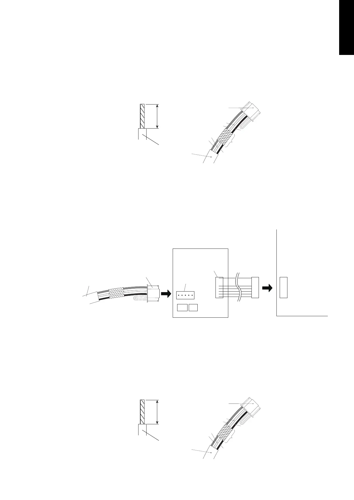
Pattern B
1. Modify the remote controller cable as follows:
• Use a tool to cut off the terminal on the end of the remote controller cable and then
remove the insulation from the cut end of the cable as shown in following figure.
• Connect the remote controller cable and connecting cable as shown in following figure.
• Be sure to insulate the connection between the cables.
13/16 in.
(20 mm)
Remote controller cable
Connecting
cable
White
Red
White
Red
Black
Insulated
connection
Black
2. Connect the remote controller cable.
• Connect the cable made in step 1. to the terminal (*1) of optional communication kit.
• Connect the cable from the terminal (*2) of communication kit to the indoor unit PCB.
*1: CNC01 (for LU type: UTY-TWBXF)
CNC01 (for LM type: UTY-XCBXZ2)
*2: CND01 (for LU type: UTY-TWBXF)
CNC01 (for LM type: UTY-XCBXZ2)
Remote controller cable
Connecting cable Terminal
(*1)
Terminal
(*2)
Communication kit
Indoor unit PCB
Pattern C
1. Modify the remote controller cable as follows:
• Use a tool to cut off the terminal on the end of the remote controller cable and then
remove the insulation from the cut end of the cable as shown in following figure.
• Connect the remote controller cable and connecting cable as shown in following figure.
• Be sure to insulate the connection between the cables.
13/16 in.
(20 mm)
Remote controller cable
Connecting
cable
White
Red
White
Red
Black
Insulated
connection
Black
- 193 -
MULTI TYPE
5, 6 ROOMS TYPE
 Loading...